


14 Plow Assembly
3. Gently tip the plow assembly to its working
position with a hoist or forklift. Pin the park-
ing stand to hold the push frame parallel to
the ground.
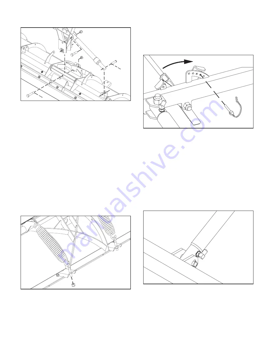
DWG NO. 5696
Swing the lift frame up to its approximate
working position and hold with a hoist or
forklift for installation of the lift cylinder.
The bottom surface inside the two prong re-
ceiver channels should measure about 10
inches above the ground in the working po-
sition.
4. Locate the 90
O
O-ring/flare adapter in the
hardware bag from the parts box.
DWG NO. 5699
Install the O-ring end of the 90
O
fitting into the
lift cylinder port so that the flared end points
toward the rod end when tightened.
Pin the lower end of the lift cylinder between
the lugs on the frame assembly with the hard-
ware provided. The 90
O
adapter should be on
the RH side of the cylinder.
DWG NO. 5698A
Install the 3/4 inch x 4 1/4 inch hex bolt re-
moved earlier so the bolt head is retained
by the lock plate on the push frame. Secure
the assembly with the 3/4 inch slotted nut
and cotter pin so the plow blade is free to
pivot.
Use clevis pins and cotter pins to fasten the
hydraulic cylinder rods between lugs on the
moldboard. Cylinder ports should be direct-
ed up.
2. From the parts box, remove two extension
springs.
Inside the hardware bag, find two threaded
spring studs and two 5/8 inch nylon insert
lock nuts.
DWG NO. 5692A
Slide a spring stud onto each spring, then
assemble springs between lugs on the
moldboard pivot tube and channels along
the upper edge of the blade.
Tighten lock nuts until spring coils begin to
separate.