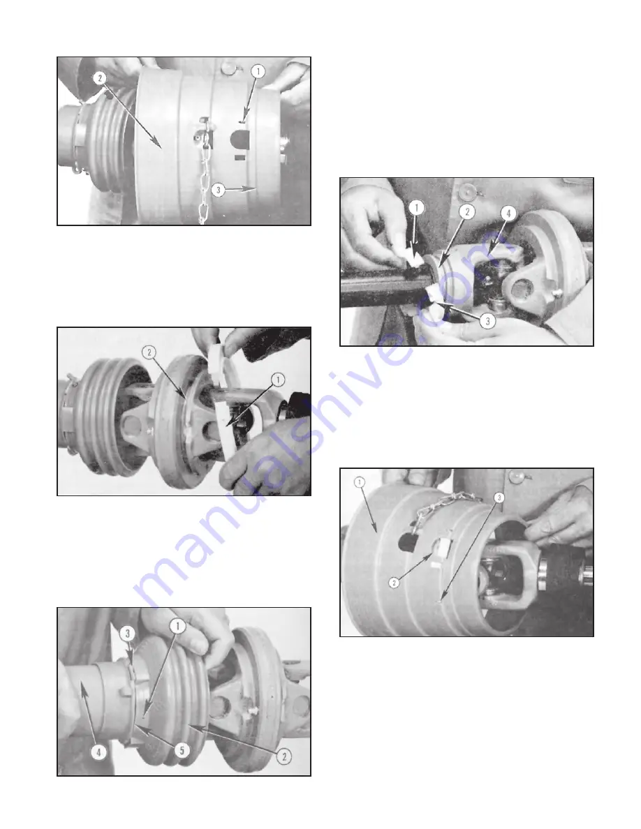
Service 31
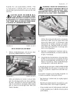
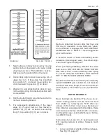
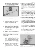
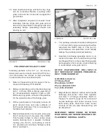
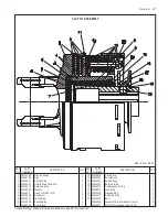
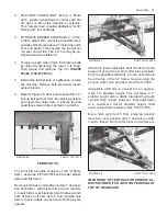
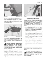
FIGURE 64 PHOTO NO. 3036
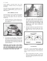
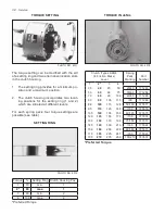
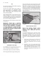
2. Remove, clean and inspect large bearing ring
Item 1 in Photo 3037. Replace if worn or dam-
aged. Clean ring track Item 2 and thoroughly
relube it, as well as bearing ring, before reas-
sembly.
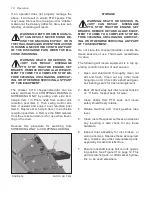
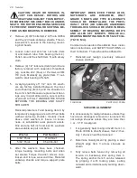
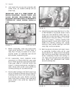
FIGURE 65 PHOTO NO. 3037
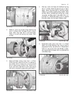
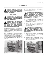
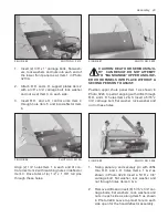
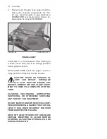
3. Remove Phillips locking screw Item 1 in Photo
3038 and rotate shield cone Item 2 to disassem-
bly position Item 3. Snap cone and tube shield
free of small plastic bearing ring. Shield cone
Item 2 and tube shield Item 4 can be pryed apart
with a flat screwdriver applied along area Item 5.
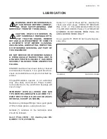
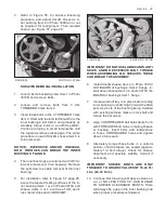
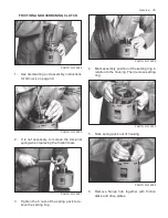
FIGURE 66 PHOTO NO. 3038
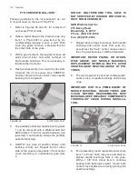
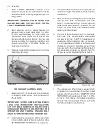
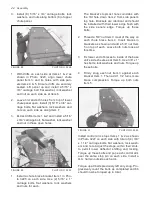
4. Remove, clean and inspect small bearing ring
Item 1 in Photo 3039. Replace if worn or dam-
aged. Clean ring track Item 2 and thoroughly
relube it, as well as bearing ring, before reas-
sembly. When reinstalling bearing ring, insure
recesses and tabs Item 3 are AWAY from “U”
joint Item 4. Reinstall shield cone in original
locked position and reinsert Phillips screw.
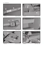
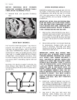
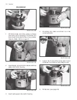
FIGURE 67 PHOTO NO. 3039
5. Reinstall double yoke cone Item 1 in Photo
3040 over large bearing ring. Insure zerk is
aligned with cone cut out Item 2. Check that 6
holes for previously removed Phillips screws
are aligned with recesses Item 3 provided and
reinstall screws.
FIGURE 68 PHOTO NO. 3040
Summary of Contents for 5710
Page 2: ......
Page 50: ...NOTES 48 Notes ...

