Assembly 43
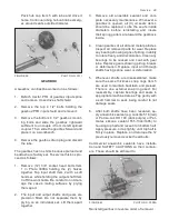
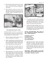
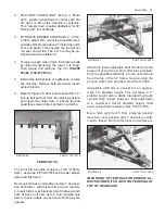
FIGURE 85 PHOTO NO. 3213
1. Insert (2) 3/8” x 1” carriage bolts, flat wash-
ers, lock washers and nuts into each end of
the lower front panel as at Item 1 in Photo
3213A.
2. Attach R.H. and L.H. support plates Item 2
with a 3/8” x 3/4” carriage bolt, lock washer
and nut as at Item 3 on each side.
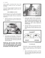
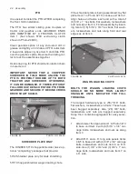
3. Insert R.H. and L.H. control arms Item 4
through hole Item 5 and into deflector Item
6.
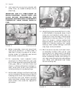
FIGURE 86 PHOTO NO. 3213A
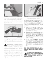
Align (2) 1/4” holes Item 1 in each end of con-
trol arms Item 2 with matching holes in deflector
Item 3. Drive total of (4) 1/4” x 1 3/8” roll pins
through these holes.
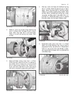
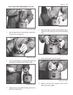
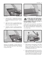
FIGURE 87 PHOTO NO. 3229
CAUTION: DEATH OR SERIOUS INJU-
RY CAN RESULT. DO NOT ATTEMPT
TO “MANHANDLE” UPPER AND LOW-
ER HOOD PANELS INTO PLACE WITHOUT A
SECOND PERSON TO ASSIST.
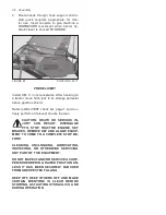
Position upper chute panel Item 1 as shown in
Photo 3226 to permit aligning with drifts through
R.H. and L.H. holes Items 2 & 3. Insert a 5/16” x
3/4” carriage bolt, flat washer, lock washer and
nut in these holes.
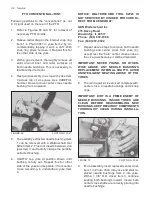
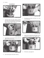
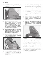
FIGURE 88 PHOTO NO. 3226
1. Swing panel up and securely pin with drifts
thru R.H. and L.H. holes Items 1 & 2 as
shown in Photo 3228. Insert a 5/16” x 3/4”
carriage bolt, flat washer, lock washer and
nut through holes Items 3 & 4.
2. Remove drifts and insert (6) 5/16” x 3/4” car-
riage bolts, flat washers, lock washers and
nuts in each side as along Item 5 as shown
in Photo 3228. Leave top most hole on each
side open for the hood-deflector assembly.
Summary of Contents for 5710
Page 2: ......
Page 50: ...NOTES 48 Notes ...

