background image

Lubrication  21

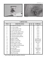
FIGURE 48                                            PHOTO NO. 4015

FIGURE 49                                          PHOTO NO. 2976B

LUBRICATION

ITEM

IDENTIFICATION

NO.

INTERVAL

1
2
3
4
5
6
7
8
9

10

11

12
13
14
15
16
17
18
19

C.V. PTO Front Cross
C.V. PTO Shield
C.V. PTO Double Yoke
C.V. PTO Rear Cross
PTO Front Rotating Shield
PTO Sliding Engagement
PTO Rear Center Cross
PTO Rear Rotating Shield
Overrun Clutch
Gearbox Fill Plug
Gearbox Check Plug
Gearbox Drain Plug
Cross Shaft Connection
Cross Shaft Outer Bearings
L.H. Rotor Bearing
Ratchet Jack
Rockshaft Bearings
R.H. Rotor Bearing
Wheel Bearings

1
1
1
1
1
1
1
1
1
1
1
1
2
1
1
2
4
1
2

8 Hr.
8 Hr.

8 Hr.*

8 Hr.
8 Hr.
8 Hr.
8 Hr.
8 Hr.

N.A.

SEASONAL*
SEASONAL*

300 HR. *

8 Hr.
8 Hr.
8 Hr.

PERIODIC

WEEKLY

8 Hr.

WEEKLY

* SEE PRIOR SPECIFIC INSTRUCTIONS

Summary of Contents for 5710

Page 1: ...CHOPPER SHREDDER MODEL 5710 WITH IDENTIFICATION No s ENDING 100 AND HIGHER OPERATOR S MANUAL DO NOT USE OR OPERATE THIS EQUIPMENT UNTIL THIS MANUAL HAS BEEN READ AND THOROUGHLY UNDERSTOOD PART NUMBER 79202099 ...

Page 2: ......

Page 3: ... RIGHT means view ing the equipment from the rear and facing the tractor This Operator s Manual is shipped with this equipment If it has not been supplied to you contact your HINIKER dealer for a replacement ALWAYS OBTAIN ORIGINAL HINIKER SER VICE PARTS BECAUSE SUBSTITUTE PARTS COULD ADVERSELY AFFECT EQUIPMENT PERFORMANCE AND WARRANTY All photos in this manual refer to paragraph s preceeding the p...

Page 4: ... Tractor 11 GENERAL Specifications 47 To Purchaser 1 Storage 18 LUBRICATION 19 21 OPERATION General 16 17 Height Adjustment 17 Shredding or Chopping 18 SAFETY Before Operation 4 Decal Location 7 10 During Operation 5 General 3 4 Service 6 Towing 5 SERVICE Belts 24 25 Drive Shaft Bearing 28 Gearbox 29 30 Hardware 23 Knives 23 24 PTO 30 38 Rotor Bearings 25 26 Shearbar 24 Sheaves 26 28 Wheel Bearing...

Page 5: ...safe ty hazard It is a reminder for observing the stated precautions and what can happen if they are ignored Decals of this class are red and white SAFETY There are other decals and copy in this manual that pertain to protecting the equipment They are not directly related to operator safety These have black letters on a white background to distinguish them from safety decals They lack the safety a...

Page 6: ...promising safety and performance 16 Do not substantially operate tractor in a closed building 17 Ag chemicals can be dangerous Always fol low the manufacturer s label safety precau tions when using them 18 Do not assume everyone is as safety con scious as yourself BEFORE OPERATION 1 Insure unit s PTO assembly is fully engaged with gearbox and tractor shafts and SLID ING COLLARS ARE RETURNED TO THE...

Page 7: ...er ous jacknifing or loss of steering control un der certain circumstances Inadequate tractor size and or ballasting Excessive towing speed Poor tractor brakes Hilly operation in combination with any of the above TOWING 1 When towing on public highways Use an aftermarket safety towing chain be tween the trail hitch and the towing tractor Use a tractor of sufficient size and weight re quired for field...

Page 8: ...e equipment Placing any part of your body in dangerous proximity to chopper shredder 3 Do not service or otherwise handle a chop per shredder in a raised position unless it is securely blocked against unexpected falling 4 Chopper shredders operate in a naturally vibra tory environment Discipline yourself to always visually inspect this equipment for any exces sively worn damaged or cracked parts b...

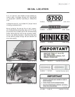
Page 9: ...emperatures should be above 50 F To ap ply remove the smaller part of the decal backing paper and apply this part of the exposed adhe sive to the desired location Peel the other part of the backing paper slowly off and smooth out the entire decal FIGURE 2 PHOTO NO 3219 FIGURE 3 PHOTO NO 3220 FIGURE 4 71505166 LOGO 5700 FIGURE 5 71505168 LOGO Hiniker FIGURE 6 71505168 LOGO Hiniker FIGURE 7 71504136...

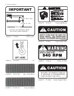
Page 10: ...PTO 8 MIN 12 MAX 540 RPM 13 TO 20 FIGURE 10 71504146 Important Hitch FIGURE 11 715 03174 Lift FIGURE 12 850 001 285 Tape Yellow Reflector FIGURE 13 850 001 305 Tape Red Reflector FIGURE 14 71504149 Caution Read Manual FIGURE 15 71504135 Caution Safety Chain FIGURE 16 71504128 Caution 540 RPM FIGURE 17 715 03056 Caution Reverse 25 MPH ...

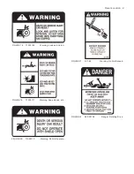
Page 11: ...ion 9 FIGURE 18 71505169 Warning Look and Listen FIGURE 19 71505171 Warning Keep Hands etc FIGURE 20 71505170 Warning Do Not Operate FIGURE 21 D11 82 Warning Do Not Exceed FIGURE 22 520 03138 Danger Rotating Drive ...

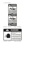
Page 12: ...10 Decal Location FIGURE 23 520 03139 Danger Shield Missing FIGURE 24 71504131 Danger Keep Flippers ...

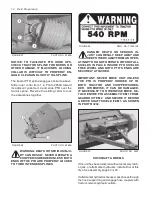
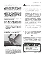
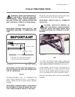
Page 13: ...own in Photo 3555A to match various tractor drawbar heights IMPORTANT CORRECT DRAFT LINK LENGTH ADJUSTMENT CANNOT BE MADE UNTIL AF TER THE MACHINE IS INITIALLY FIELDED Raise the unit with hitch jack until the hitch yoke corresponds with the tractor s drawbar IMPORTANT ALWAYS USE A 1 DIAMETER HITCH PIN CAUTION DEATH OR SERIOUS IN JURY CAN RESULT ALWAYS INSERT THE HITCH PIN POINT DOWN WITH ACROSS LO...

Page 14: ...504128 DANGER DEATH OR SERIOUS IN JURY CAN RESULT KEEP AWAY AND KEEP OTHERS AWAY FROM AN OPER ATING PTO DO NOT OPERATE WITHOUT ALL SHIELDS IN PLACE INSURE PTO SHIELDS FREE WHEEL AND BOTH PTO S ENDS ARE SECURELY ATTACHED IMPORTANT NEVER MOVE UNIT UNLESS THE PTO IS PROPERLY HOOKED UP TO BOTH TRACTOR AND CHOPPER SHRED DER OTHERWISE IT CAN BE DAMAGED IF NECESSARY TO OTHERWISE MOVE DE TACH ENTIRE PTO A...

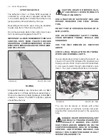
Page 15: ...tract lift sufficient for tires to clear the ground Do this with unit hitched to a tractor of adequate size to stabilize it CAUTION DEATH OR SERIOUS IN JURY CAN RESULT MAKE ADJUST MENTS ONLY ON A LEVEL SURFACE SET TRACTOR S BRAKES AND SHUT OFF THE ENGINE BEFORE PROCEEDING 3 Loosen the 6 5 8 leg bolts in each wheel and transversely slide the entire wheel as sembly FOR ROW CROPS ONLY position wheel l...

Page 16: ...3233A CAUTION DEATH OR SERIOUS INJU RY CAN RESULT WHEN TOWING ON PUBLIC HIGHWAYS USE A TRACTOR OF SUFFICIENT SIZE AND WEIGHT REQUIRED FOR FIELD OPERA TION DO NOT TOW AT SPEEDS IN EXCESS OF 25 MPH 40 KPH USE AN AFTERMARKET SAFETY TOWING CHAIN BETWEEN TOWING VEHICLE AND SHREDDER USE THE SMV EMBLEM AS SPECIFIED ABOVE CHECK LOCAL REGULATIONS ON TOWING WIDTH AND WARNING LIGHTS Use an aftermarket safety...

Page 17: ...D OR BALLASTING CAUTION DEATH OR SERIOUS IN JURY CAN RESULT WHEN TOWING A CHOPPER SHREDDER AND TRAILING WAGON ON PUBLIC HIGHWAYS OBSERVE PRIOR TOWING SAFETY GUIDELINES AND IN ADDITION USE AN AFTERMARKET SAFETY TOWING CHAIN BETWEEN CHOPPER SHREDDER AND TRAILING WAGON KEEP A SMV EMBLEM ON THE TRAILING WAGON ...

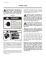
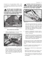
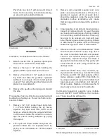
Page 18: ... IN JURY CAN RESULT SOME TRACTOR MASTER PTO SHIELD S MAY CON TACT THE UNIT S FRONT PTO SHIELD ON TURNS BE ALERT FOR THIS AND MAXI MIZE TURNING RADII REPLACE FRONT PTO SHIELD IF IT BECOMES DAMAGED CAUTION DEATH OR SERIOUS INJU RY CAN RESULT NEVER STAND BE HIND LOADING SPOUT OR IN TRAIL ING WAGON WHEN FLYING MATERIAL IS IMPACTING IMPORTANT INITIALLY START CHOPPING SHREDDING WITH UNIT SET SUBSTANTIAL...

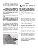
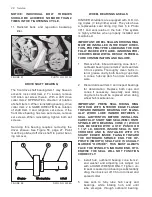
Page 19: ... FIGURE 52C PHOTO NO 3548 At this time remove bolts and or pin adjust ment from draft link see figure 52C and proceed to adjust jack in combination with wheel arms to achieve desired unit profile see figure 38 Reattach draft link and re move hitch jack and return to storage posi tion on top of gearbox 2 Recheck knives ground clearance and re adjust rockshaft wheels as well as draft link length if nec...

Page 20: ...is procedure for switching from SHREDDING ONLY to CHOPPING LOADING FIGURE 39 PHOTO NO 3224 STORAGE WARNING DEATH OR SERIOUS IN JURY CAN RESULT DISENGAGE PTO STOP TRACTOR ENGINE SET BRAKES REMOVE KEY AND ALLOW EQUIP MENT TO COME TO A COMPLETE STOP BE FORE CLEANING UNCLOGGING LUBRICAT ING OR OTHERWISE SERVICING ANY PART OF THIS EQUIPMENT Do not store the chopper shredder outside be tween seasons of ...

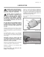
Page 21: ...relubricate a unit prior to first field op eration Chopper Shredders operate in an extremely dirty fine dust environment Proper mainte nance attention to the anti friction bearings will save money IMPORTANT WIPE ALL ZERKS AND GUN TIPS BEFORE LUBRICATING ADHERE TO 1 PUMP PER FITTING ON AN 8 HOUR DAILY INTERVAL EXCEPT AS SHOWN Replace any damaged fittings Use a good grade of lithium base grease except a...

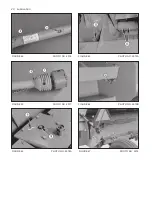
Page 22: ...20 Lubrication FIGURE 42 PHOTO NO 4016 FIGURE 43 PHOTO NO 4017 FIGURE 44 PHOTO NO 2978A FIGURE 45 PHOTO NO 2973A FIGURE 46 PHOTO NO 2975B FIGURE 47 PHOTO NO 3233 ...

Page 23: ... PTO Sliding Engagement PTO Rear Center Cross PTO Rear Rotating Shield Overrun Clutch Gearbox Fill Plug Gearbox Check Plug Gearbox Drain Plug Cross Shaft Connection Cross Shaft Outer Bearings L H Rotor Bearing Ratchet Jack Rockshaft Bearings R H Rotor Bearing Wheel Bearings 1 1 1 1 1 1 1 1 1 1 1 1 2 1 1 2 4 1 2 8 Hr 8 Hr 8 Hr 8 Hr 8 Hr 8 Hr 8 Hr 8 Hr N A SEASONAL SEASONAL 300 HR 8 Hr 8 Hr 8 Hr PER...

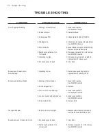
Page 24: ...ly 3 above rows 8 Excessive ground speed 8 Slow down Excessive knife wear and or stone damage 1 Operating too low 1 Raise knives operating height to approximately 3 above ground Excessive shredder vibration 1 Missing or broken knives 1 Inspect and replace See SERVICE section 2 Rock damaged rotor 2 Replace 3 Worn or loose rotor bearings 3 Inspect and maintain See SERVICE section 4 Loose or misalign...

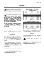
Page 25: ...NIKER machines are EQUIPPED ONLY WITH GRADE 5 BOLTS 3 marks on heads Many are retained with TYPE B or F LOCKNUTS Type B locknuts are PLAIN hex Type F locknuts are FLANGED hex IMPORTANT DO NOT REPLACE HARDWARE WITH LOWER GRADE ITEMS EXCEPTING ON SHEAVES PAGE 27 ALL BOLT TORQUE VALUES ARE GRADE 5 HARDWARE OVER OR UNDER TORQUING CAN RESULT IN UN SATISFACTORY DURABILITY GRADE 5 TYPE B F LOCKNUT TORQUE...

Page 26: ...justment It is factory adjusted to the furthermost FORWARD position Item 2 This provides 3 4 theoretical clearance from the rotor knives As rotor knives wear or better chopping shredding is needed move the shearbar rearward If knives are worn unevenly hold LONGEST knife out toward cutterbar to check clearance It is not recommended to adjust the shearbar closer than 1 4 to the rotor knives CLOSER S...

Page 27: ...SING ON V BELTS This will aggravate poor belt function If evidence exists of belts overheating and or excessive side wrapper wear check belt align ment See Figure 55 page 27 When purchasing installing matched belt sets take care to NOT MIX BELTS FROM DIFFER ENT SETS Also loosen backwrap idler spring to provide adequate installation slack NEVER PRY V BELTS OVER SHEAVE RIMS Replacement belt sets sho...

Page 28: ...ers are available as part numbers Washer Part Number 3 64 Thick 710 05321 5 64 Thick 952 004 041 6 After the washers have been checked torque bearing mounting bolts and Allen set screws Torque the Allen screws once loosen and torque a second time Reinstall antiwrap shields and torque support plate bolts IMPORTANT WHEN EVER THESE LOCK NUTS BOLTS ARE DISCARDED ONLY GRADE 5 BOLTS AND TYPE B LOCKNUTS ...

Page 29: ...UB FLANGE TO SHEAVE CLEARANCE EXISTS There will always be a gap in the inner bushing hub when proper procedure is followed 4 Refer to Figure 56 for sheave loosening procedure and adjust driveR sheave s in ner bushing Item 6 in Photo 3009A in or out as required for realignment Then reinstall sheave per Figure 57 page 28 FIGURE 55 PHOTO NO 3009A SHEAVES REMOVAL INSTALLATION 1 Loosen belt s backwrap ...

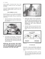
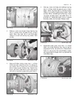
Page 30: ... HUB FULLY PACKED WITH LUBE IGNORING PRO CEDURES BELOW WILL RESULT IN PREMA TURE CONTAMINATION AND FAILURE 1 Remove hub inboard bearing cone Item 1 outboard bearing cone Item 2 and seal Item 3 from spindle Thoroughly clean hub s in terior grease cavity both bearing cups Item 4 cones hub cap Item 5 and pre load hard ware 2 Discard old seal Item 3 and inspect bearings for deterioration Replace both ...

Page 31: ...maintenance Whenever a gearbox is opened all 3 oil seals Item 4 should be replaced Lube the seal s inside diameters before reinstalling and insure their spring garters are toward the gearbox s inside 4 Clean gearbox of all dirt and metal particles Inspect all removed parts for wear Replace any bearing showing signs of pitting inability to rotate freely and discoloration Clean any bearings to be re...

Page 32: ...prings from the external enclosure IMPORTANT PARTICULARLY NOTE DIREC TION OF ORIGINAL FACTORY CLUTCH KEYS AND LEAF SPRINGS INSTALLATION INSURE CLUTCH IS REASSEMBLED THE SAME WAY OTHERWISE IT WILL NOT FUNCTION FIGURE 62 PHOTO NO 3034 3 Clean entire clutch and lock collar assem bly Replace broken or worn parts and re assemble with leaf springs between internal step of driving keys and clutch hub OB ...

Page 33: ...iver applied along area Item 5 FIGURE 66 PHOTO NO 3038 4 Remove clean and inspect small bearing ring Item 1 in Photo 3039 Replace if worn or dam aged Clean ring track Item 2 and thoroughly relube it as well as bearing ring before reas sembly When reinstalling bearing ring insure recesses and tabs Item 3 are AWAY from U joint Item 4 Reinstall shield cone in original locked position and reinsert Phi...

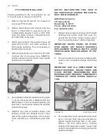
Page 34: ...at this for other side of the yoke and separate it from center cross remaining in undisturbed yoke Item 4 NOTICE WALTERSCHEID TOOL SW23 IS NOT SERVICED BY HINIKER PROCURE DI RECT FROM VENDOR AT GKN Walterscheid Inc 275 Davey Road Woodridge IL 60517 Phone 630 972 9300 Fax 630 972 9392 7 Repeat above steps to remove both needle bushings and center cross from yoke 4 except rest the bare center cross ...

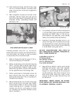
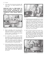
Page 35: ...ith outer yoke Item 3 across top of vice jaws Use CARE FUL hammer blows to drive center cross needle bushing Item 4 upward Vertically rocking yoke Item 5 as bushing is driven out provides ear clearance between yokes Item 2 and Item 3 FIGURE 72 PHOTO NO 3044 5 The partially extracted needle bushing Item 1 in Photo 3045 can be removed with a Wal terscheid tool SW23 Item 2 This tool in serts between ...

Page 36: ...oth snap rings can be reinserted Repeat above steps for installing center cross and needle bushings in remaining outer yoke Before mounting either outer yoke to flange yokes assembly insure center cross zerks are aligned for gun access FIGURE 74 PHOTO NO 3046 12 Clamp flange yokes assembly Item 1 in Pho to 3047 between vice jaws as shown Insert outer yoke and replaced center cross as sembly Item 2 i...

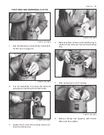
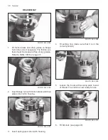
Page 37: ... spring when replacing the friction disks PHOTO NO 4001 3 Tighten the 6 nuts of the spring pack to re lieve the setting ring Service 35 PHOTO NO 4002 4 Mark assembly position of the setting ring in relation to the housing Then remove setting ring PHOTO NO 4003 5 Take spring pack out of housing PHOTO NO 4004 6 Remove flange hub together with friction disks and drive plates ...

Page 38: ...WG 3676 on page 37 PHOTO NO 4006 2 Insert flange hub with friction disks and drive plates into clutch housing PHOTO NO 4007 3 Insert spring pack into clutch housing PHOTO NO 4008 4 Fit setting ring make sure that it is in the correct position PHOTO NO 4009 5 Loosen the 6 nuts at the spring pack to end of thread The clutch is now ready for use PHOTO NO 4010 6 Fit QC lock see page 30 ...

Page 39: ...ing Ring Washer Hub 1 3 8 6SPL QD Key 50mm Leaf Spring Sealing Ring Drive Plate 1 1 4 1 2 2 1 2 2 1 1 12 13 14 15 16 17 18 19 20 52003202 52003200 52003204 52003213 52003214 52003215 52003216 52003217 52003218 52003219 52003212 Drive Plate Spring Pack Setting Ring Back Up Ring Compression Spring Lock Ring Flanged Ring Retaining Ring Ball Locknut M8 ln Included in Item 3 QD FLG Kit Includes Item 15...

Page 40: ...ee table SETTING RING PHOTO NO 4012 Torque Setting Ring Clutch Housing Pos 1 70 min 1 2 80 max 1 3 90 min 2 4 100 max 2 Preferred Torque TORQUE IN daNm PHOTO NO 4018 Clutch Types K96 4 4 Friction Disks Level Spring Pack Marking Part Number 1 2 3 4 35 40 45 50 20 40 171283 53 60 68 75 30 60 171284 70 80 90 100 40 80 171285 80 90 105 115 90 171286 88 100 115 128 50 100 377677 95 110 125 140 100 3776...

Page 41: ...re shown by decals Item 3 Lift off carrier and deposit on a firm clear and level work area FIGURE 76 PHOTO NO 3212 ASSEMBLY Discharge chute components and hitch are shipped in separate bundles CAUTION DEATH OR SERIOUS INJU RY CAN RESULT DO NOT ATTEMPT TO MANHANDLE THE HITCH OR MAIN TRAPEZOIDAL CHUTE PANELS WITHOUT PROPER ASSISTANCE Eg THE HITCH WEIGHS 125 Lbs 57 Kg 1 The drive enclosure Item 1 as s...

Page 42: ...NTERLINE 2 Install either an accessory ratchet jack Item 4 or an aftermarket hydraulic cylinder See AFTERMARKET HYDRAULICS page 45 3 Contract either ratchet jack or hydraulics to minimum length This permits wheel and tire installation 4 Each wheel leg is clamped to the rockshaft with 6 5 8 bolts lockwashers and nuts Item 5 Install wheel legs in their approxi mate transverse position however do not...

Page 43: ...undle consists of the A frame Item 1 as shown in Photo 3555 and a lower adjust able draft link Item 2 Remove both base unit draft pins Item 3 and posi tion hitch Item 1 with thicker hitch clip on top Item 4 Insert hitch s rear brackets Item 5 between both sets of base unit ears Item 6 and reinstall pins Item 3 Insure cotters on each end of both pins are spread FIGURE 81 PHOTO NO 3555 Attach the lo...

Page 44: ...2 Shredder plate only for stalk shredding 5701 Chopper shredder wagon loading chute If the shredder plate is being assembled lay flat plate Item 1 in Photo 3218 on base unit Item 2 Align holes and fasten each end with a total of 6 3 8 x 1 hex bolts flat washers lockwashers and nuts as at Item 3 Finish assembly by insert ing total of 16 5 16 x 3 4 hex bolts flat wash ers lockwashers and nuts along fro...

Page 45: ... 3229 CAUTION DEATH OR SERIOUS INJU RY CAN RESULT DO NOT ATTEMPT TO MANHANDLE UPPER AND LOW ER HOOD PANELS INTO PLACE WITHOUT A SECOND PERSON TO ASSIST Position upper chute panel Item 1 as shown in Photo 3226 to permit aligning with drifts through R H and L H holes Items 2 3 Insert a 5 16 x 3 4 carriage bolt flat washer lock washer and nut in these holes FIGURE 88 PHOTO NO 3226 1 Swing panel up and...

Page 46: ...tem 2 from side panel s top hole Brackets are identical and should be installed with their lower edge flush with the side panel s edge Torque up these bolts 2 Thread a 5 8 nut Item 3 most of the way on each chute brace Item 4 Insert braces in brackets as shown and add a 5 8 nut Item 5 on top of each Leave both nuts loose at this time 3 Fix lower end of braces to inside of the base unit s side sheet...

Page 47: ...he unit includes a hose support Item 1 as shown in Photo 3217 on page 46 and a hose clamp Item 2 HINIKER sup plies hydraulic cylinders hoses and fittings as optional equipment Hydraulic couplers are not provided 1 Install hose support to the rear R H gear box shield at bolt Item 3 Ensure the original flat washer is BETWEEN the bolt head lock washer and the hose support 2 Prepare 2 hydraulic hoses ea...

Page 48: ...IVERY check list page 1 and rou tinely perform all relevant checks thereon CAUTION DEATH OR SERIOUS IN JURY CAN RESULT DISENGAGE PTO STOP TRACTOR ENGINE SET BRAKES REMOVE KEY AND ALLOW EQUIP MENT TO COME TO A COMPLETE STOP BE FORE CLEANING UNCLOGGING LUBRICATING INSPECTING OR OTHERWISE SERVICING ANY PART OF THIS EQUIPMENT DO NOT INSPECT AND OR SERVICE A CHOP PER SHREDDER IN A RAISED POSITION UN LE...

Page 49: ...TO w Friction OVR Clutch Standard Premium Matched C Drive Belts 2 Recommended Tires Standard 15 x 5KB 6 Bolt Wheels 7 60 x 15 4PR l1 or equal Approx Weight W Loading Spout Tires Ratchet Jack 1850 839 kg Approx Weight W Shredding Plate Tires Ratchet Jack 1550 703 kg Spout Deflector Control Rope Optional Equipment 5710 Basic W O Loading Spout 805 001 154 7 60 x 15 6 Ply Tires 000 04097 Ratchet Lift J...

Page 50: ...NOTES 48 Notes ...
Page 51: ...use operation beyond rated capacity reasonable intended use substitution of parts not approved by us or any alteration or repair by others in such manner as in our judgement affects the product materially and adversely shall void this warranty NO EMPLOYEE OR REPRESENTATIVE IS AUTHORIZED TO CHANGE THIS WARRANTY IN ANY WAY OR GRANT ANY OTHER WARRANTY HINIKER reserves the right to make improvement ch...

Reviews: