


HARDWARE
4
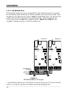
Figure 1
EN5004-0
#
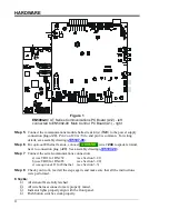
AT Series Communications PC Board (A12) -
left
connected to EN5002-00 Main Control PC Board (A1) -
right
Step 5
Connect the communications module ballast resistor(s) (
R29
) to the power supply
connection plug (
J20
). Pin 2 on J20 is +Vdc, and pin 4 is common. For wiring
details, see assembly drawing (
Step 6
For
optional
Ethernet feature, connect
.
GROUND
.
wire #
244
to spade terminal,
next to connection plug (
J20
). See assembly drawing (
Step 7
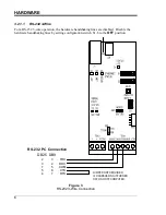
Connect the serial communications connection:
a) use TB11 for RS-232
(see Section 3.2.1)
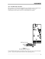
b) use TB10 for RS-485
(see Section 3.2.2)
c)
use
optional
J1 for Ethernet
(see Section 3.3)
Step 8
Check your work, read all the steps again, and make sure that all the instructions
were performed.
Checks:
All stand-offs are fully latched.
All wire harness connectors are properly mated.
Indicator lights properly align with the front panel.
Push button switches work properly.