4 Start-up
X-MIO 7/6 01
Page 60 of 72
HI 801 305 E Rev. 5.00
4.6.2
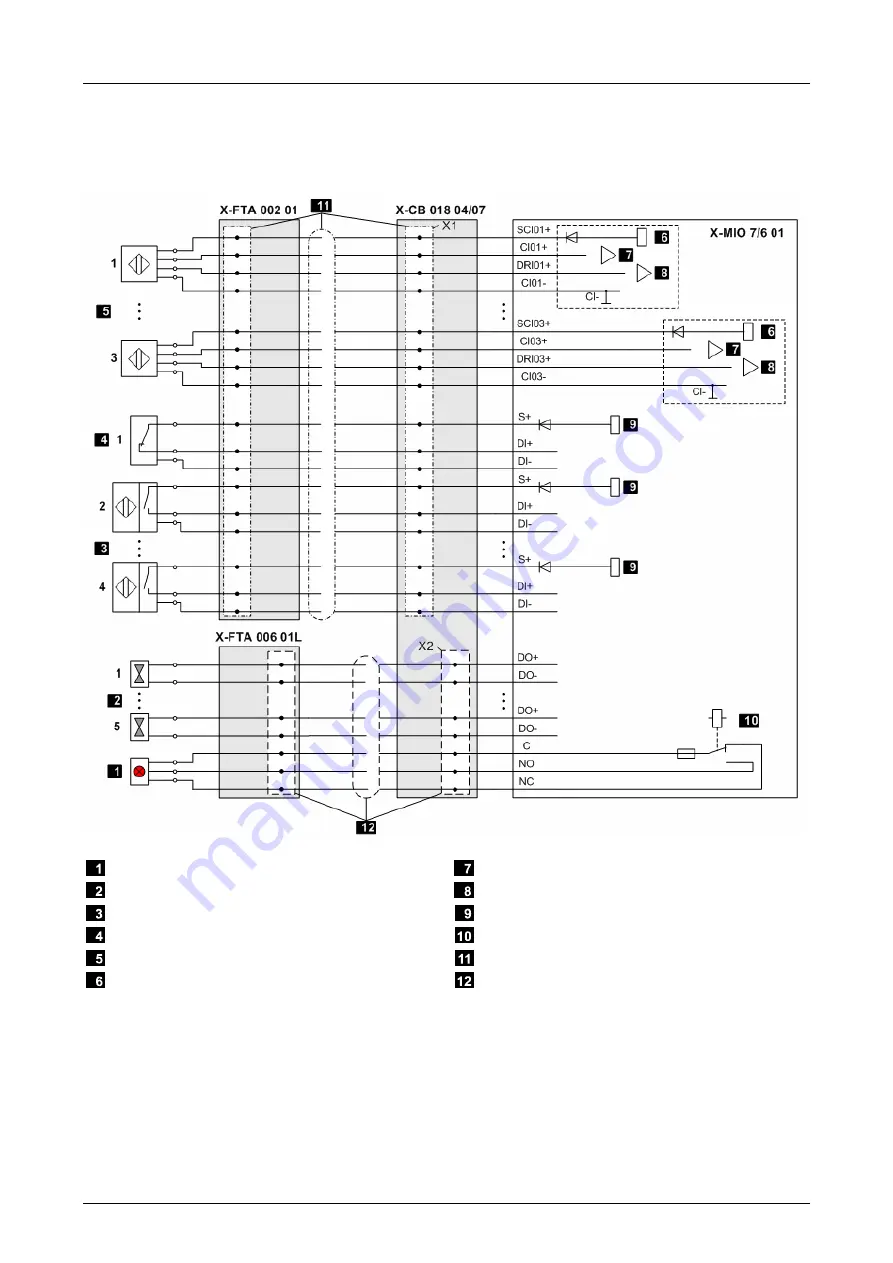
Wiring the Modules via FTA using System Cables
The following figure only depicts the wiring for one module. The inputs and outputs of the
redundant modules are connected in parallel via connector boards to the sensors and actuators.
Warning Signal Device
Actuators DO 01...05 e.g., Solenoid Valves
Control Circuit Devices of Type 3, DI 02...04
Reset Input
Sensors CI 01...03
Supply for the Measuring Input
Input for Measuring the Rotation Speed
Input for Measuring the Rotation Sense
Supply for Digital Inputs
Warning Relay
System Cable X-CA 005 (X1)
System Cable X-CA 008 (X2)
Figure 15: Wiring via X-FTA


