STATUS OF THE SYSTEM
OPEN ZONES
On the second line of the display are indicated the open zones.
The leds of the open zones on the panel of the central computer
are turned on. Pay attention: the signal of the opening of the radio
zones lasts 2 seconds.
MEMORY ZONE:
It was memorized at least one zone that generated an alarm
(on the second line are indicated the numbers of the zones of the
memory and of the 24h). If you keep pressed button on the
panel, the leds of the memory zones will flash.
-24H NOT ACTIVATED: the line 24h it was never closed since when it was resetted or it was
feeded the central computer. To close the the line 24h, the tamper
of the central and of the console and the protection 24h was re-
established.
OUTPUT.....
The ongoing time of output
ENTRY.....
Time of entry ongoing. Opening of a delayed zone wen the
central is activated before that a cicle of alarm is generated.
OUTPUT ACTIVE
On the clamp +INT of the central are p12v because is an
effect of the command of the activated output.
TOTALLY INSERTED SYSTEM: Sytem inserted totally.
P-A INSERTED SYSTEM: System inserted with a scheme of patialization A.
P-B INSERTED SYSTEM:
System inserted with scheme of partialization B.
ALARM 24H
Cicle of alarm 24 h ongoing.
TOTAL ALARM
Alarm with a cantral inserted in a total way.
ALARM P-A
Alarm with the system inserted in a partial way A.
ALARM P-B
Alarm with a system inserted in a partial way B.
DEVICES 485 AND RADIO
RADIO ZONE BATTERY
Indicates that there are batteries on the radio devices to be
substituted. On the second line of the display , it will appear the
status of the batteries for each radio zone :
L
if it is charging
H
if it is charged
-
if the zone is a cabled one.
MEM 24H ZONE RF
The second line reports what radio zones activated the the
memory for the opening of the container.
MEMORY 24H SIRENS RF
Indicates that the radio sirens, generated an alarm of 24 H in order
to open a container.
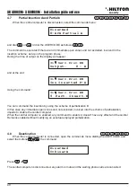
INSERTER 2 17
On the first line of the display is indicated the device with its
LINK BAD
address that doesn't communicate with the central correctly.
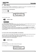
REMOTE CONSOLLE
Indicates that the tamper of the remote consolle is open and it
Tamper Open Mem
generated a cicle of alarm 24H.
REMOTE CONSOLLE
indicates that the tamper of the remote consolle is now closed, and
Tamper Close Mem
Mem it generated a cicle of alarm 24H . The reset of this memory is
carried out by inserting the system.
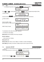
The reported information are displayed on the panel of the central and of a probabe consolle in addition and
are repeated cyclically with an authomatic timing.
Using the buttons it is possible let them scroll rapidly.
6.2
Reports on display
During the normal functioning of the central, it provides some information on the display of the panel and of the
consolle related to the status of the system, and the GSM Module.
GSM MODULE
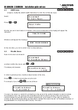
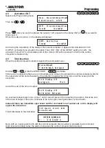
On the first line of the display it will appear the information related to the GSM connection like this:
The number next to the flashing symbol of the antenna represents the intensity of the signal from 0 (min)
to 31 (max), followed by the indication of the service provider the system is connected.
Other indication related to the GSM Module can be:
GSM OFF:
the module is off – See the programming menu , 2 – setup, GSM Module
(paragraph 3.3.23)
INIT GSM:
when the module is activated REGISTRATION: waiting for the the
confirm of the service provider of the registration of the SIM card.
REGISTRATION DENIED:
the service provider denies the registration on the SIM card.
SEND SMS:
when the module sends SMS.
CALL:
during an attempt of phone call.
CONNECTED:
ongoing phone connection. OCCUPIED : the called number is occupied.
CALL FAILED:
the called number refused the connection.
CALL ENDED:
the phone connection is interrupted.
INSERT SIM:
SIM card missing.
SIM WITH THE PIN:
you need to cancel the PIN code from the SIM card using a mobile
phone.
SI M WITH PUK:
the SIM card requires the PUK code. Use a mobile phone.
SIM ERROR:
Error during the communication with the SIM card.
GST ERROR XX:
Error of the GSM module during the initialization. Check the antenna, the
SIM card and the remaining credit. Restart the GSM module. If the
problem persists, contact the technical assistance.
CME ERROR XX:
Error on the GSM net. Wait for a minute and restart the module. Try with
an other service provider. If the problem persists, contact the technical
assistance.
Power supply
Fuse 1 out of order: if the fuse is broken F1 in this case all the cabled zones are open and the external
devices, including the console don't work. Absence of network: there is a lack of the power supply.
Missing battery: battery is missing.
Battery out of order: the battery must be substituted.
Low battery: if the problem persists the battery must be substituted.
2 5 S e r v . P r o v . E N
security
security
47
46
Use of the central unit
XR400GSM
- XR
800GSM - Installation guide and use


