


2
Installation
Before you start:
Make sure that the device in the package is in good
condition and all the assembly parts are included.
Make sure that all the related equipment is power-off
during the installation.
Check the specification of the products for the
installation environment.
Check whether the power supply is matched with
your power output to avoid the damage.
Make sure the wall is strong enough to withstand
three times the weight of the camera and the mount.
If the wall is cement, insert expansion bolts before
installing the camera. If the wall is wooden, use
self-tapping screws to secure the camera.
If the product does not function properly, contact
your dealer or the nearest service center. DO NOT
disassemble the camera for repair or maintenance by
yourself.
2.1
Installation of Type I Camera
Before you start:
Both wall mounting and ceiling mounting are suitable
for the camera. We take ceiling mounting as an example
in this section. You can take the steps of ceiling
mounting as a reference when adopting wall mounting.
Steps:
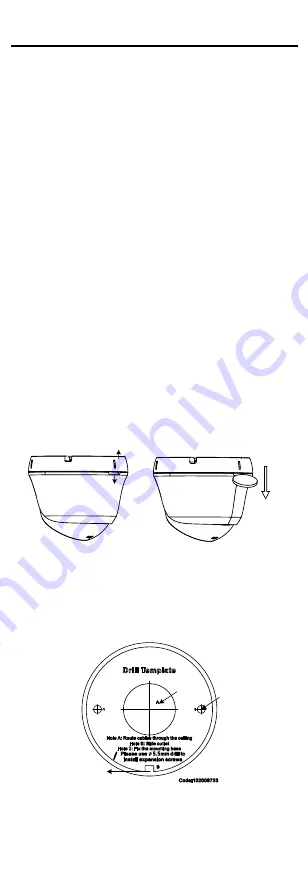
1.
Disassemble the turret camera
1)
Rotate the camera to align the notch to one of
the marks, as shown in the figure below.
Mark
Notch
Figure 2-1
Disassemble the Camera
2)
Remove the mounting base from the camera
body with a flat object, e.g., a coin.
2.
Paste the drill template (supplied) to the installation
place.
3.
Drill the screw holes, and the cable hole (optional)
on the ceiling according to the drill template.
Screw
Hole
Cable
Hole
Side
Opening
Figure 2-2
Drill Template
Note:
Drill the cable hole, when adopting the ceiling outlet
to route the cable
.
4.
Attach the mounting base to the ceiling, and secure
them with supplied screws.


