background image


2.2


Installation of Type III Camera 

Before you start: 
Both wall mounting and ceiling mounting are suitable 
for the camera. We take ceiling mounting as an example 

in this section. You can take the steps of ceiling 
mounting as a reference, when adopting wall mounting.


Steps: 

1.


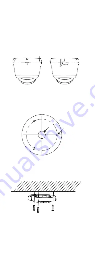
Disassemble the turret camera by rotating the 
camera to align the notch to one of the marks, as 

shown in the figure below. 

Mark

Notch


Figure 2-6


Disassemble the Camera 

2.


Remove the mounting base from the camera body 

with a flat object, e.g., a coin. 

3.


Paste the drill template (supplied) to the place 

where you want to install the camera. 

4.


Drill the screw holes and the cable hole (optional) 
on the ceiling according to the drill template. 

Screw 

Hole

Cable 

Hole


Figure 2-7


Drill Template 

Note: 

Drill the cable hole, when adopting the ceiling outlet 
to route the cable


5.


Attach the mounting base to the ceiling, and secure 
them with supplied screws 


Figure 2-8


Attach the Mounting Base to the Ceiling


Note: 


The supplied screw package contains self-tapping 
screws, and expansion bolts. 


For cement ceiling, expansion bolts are required to 
fix the camera. For wooden ceiling, self-tapping 
screws are required. 

6.


Route the cables through the cable hole, or the side 
opening. 

7.


Align the camera with the mounting base, and 

tighten the screws to secure the camera on the 
mounting base. 

Summary of Contents for THC-B110

Page 1: ...110 Type II Camera THC T120 P THC T110 P Type III Camera THC T220 P THC T210 P Type IV Camera THC B220 THC B210 Type V Camera THC B120 THC B120 P THC B110 THC B110 P This manual may contain several te...

Page 2: ...his device must accept any interference received including interference that may cause undesired operation EU Conformity Statement This product and if applicable the supplied accessories too are marke...

Page 3: ...mounting is adopted If smoke odor or noise rise from the device turn off the power at once and unplug the power cord and then contact the service center Never attempt to disassemble the camera by unpr...

Page 4: ...his manual applies to five types of cameras The overviews of each type are shown in the figures below 1 2 1 Overview of Type I Camera DC12V IN Enclosure Main Body Mounting Base Power Cord 12 VDC Video...

Page 5: ...Cable Power Cord 12 VDC Switch Button Mounting Base Main Body Lens Figure 1 4 Overview of Type IV Camera Note Press and hold the switch button for 5 seconds to switch the video output Four kinds of v...

Page 6: ...r repair or maintenance by yourself 2 1 Installation of Type I and Type II Camera Before you start Type I and type II camera share the same installation and we take type I camera as the example to des...

Page 7: ...e mounting base and tighten the screws to secure the camera on the mounting base Figure 2 4 Secure the Camera with Mounting Base 8 Connect the corresponding cables such as power cord and video cable 9...

Page 8: ...e where you want to install the camera 4 Drill the screw holes and the cable hole optional on the ceiling according to the drill template Screw Hole Cable Hole Figure 2 7 Drill Template Note Drill the...

Page 9: ...adjust the rotation position 0 to 360 2 3 Installation of Type IV and Type V Camera Before you start Type IV and Type V camera share the same installation we take Type V camera as the example to desc...

Page 10: ...d video cable 6 Power on the camera to check whether the image on the monitor is gotten from the optimum angle If not adjust the camera according to the figure below to get an optimum angle 3 2 1 Pan...

Page 11: ...MAT LANGUAGE DAY NIGHT VIDEO SETTINGS RESET SAVE EXIT EXPOSURE MODE AGC DWDR MODE RETURN CONTRAST SHARPNESS COLOR GAIN DNR RETURN RETURN Figure 3 2 Main Menu Overview 5 Click the direction arrow to co...

Page 12: ...IGH MIDDLE or LOW Select OFF to disable the GAIN function Note The noise will be amplified when the GAIN is on DWDR Digital Wide Dynamic Range The DWDR helps the camera provide clear images even under...

Page 13: ...3 3 VIDEO SETTING Move the cursor to VIDEO SETTING and click Iris to enter the submenu CONTRAST SHARPNESS COLOR GAIN and DNR are adjustable VIDEO SETTING CONTRAST SHARPNESS COLOR GAIN DNR RETURN 5 5...

Page 14: ...3 4 RESET Move the cursor to RESET and click Iris to reset all the settings to the default 3 3 5 SAVE EXIT Move the cursor to SAVE EXIT and click Iris to save the setting and exit the menu UD05432B A...

Reviews: