


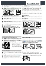
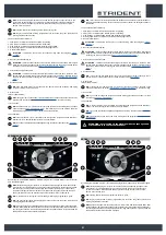
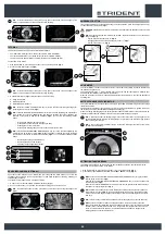
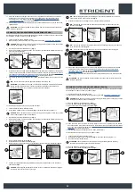
SYMBOLS USED ON THE CONTROL DISPLAY
DRIVE
0000.00
100%
1
2
3
4
5
6
7
17
19
8
16
18
9
10
12
11
13
15
14
1. HFM symbol, if visible it shows that the “HILLYARD FLEET MANAGEMENT” system is active.
2. HDC symbol, if visible it shows that the “HILLYARD DOSING CONTROL” system is active.
3. Side brush head symbol, if visible it shows that the side brush is operating.
4. Working lights symbol, if visible it shows that the working lights are on.
5. Hour meter.
6. battery charge level percentage.
7. General alarm symbol.
8.
Recovery tank float symbol, if visible it shows that the recovery tank is full and that to continue you
need to empty it.
9.
Solution tank float symbol, if visible it shows that the recovery tank is empty and that to continue
you need to fill it.
10. Detergent solution level symbol.
11. Vacuum motor performance level symbol.
12. "HILLYARD ECO-MODE" program button.
13. Working mode selector (DRIVE SELECT).
14. Rear camera symbol.
15. Menu screen activation symbol.
16. Text indicator.
17. Zone program selector button.
18. Brush head extra pressure level symbol.
19. Forward speed level symbol.
PREPARATION OF MACHINE
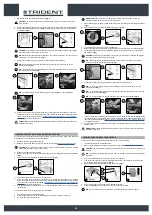
HANDLING THE PACKAGED MACHINE
The machine's overall weight including packaging is 1180 lb.
N.B.
: it is recommended that all the packaging components be kept for any future machine
transportation.
DANGER
: move the packaged product with handling equipment that complies with legal
requirements regarding size and mass of the packaging.
A
63 in
B
50 in
C
80 in
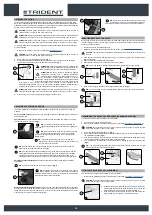
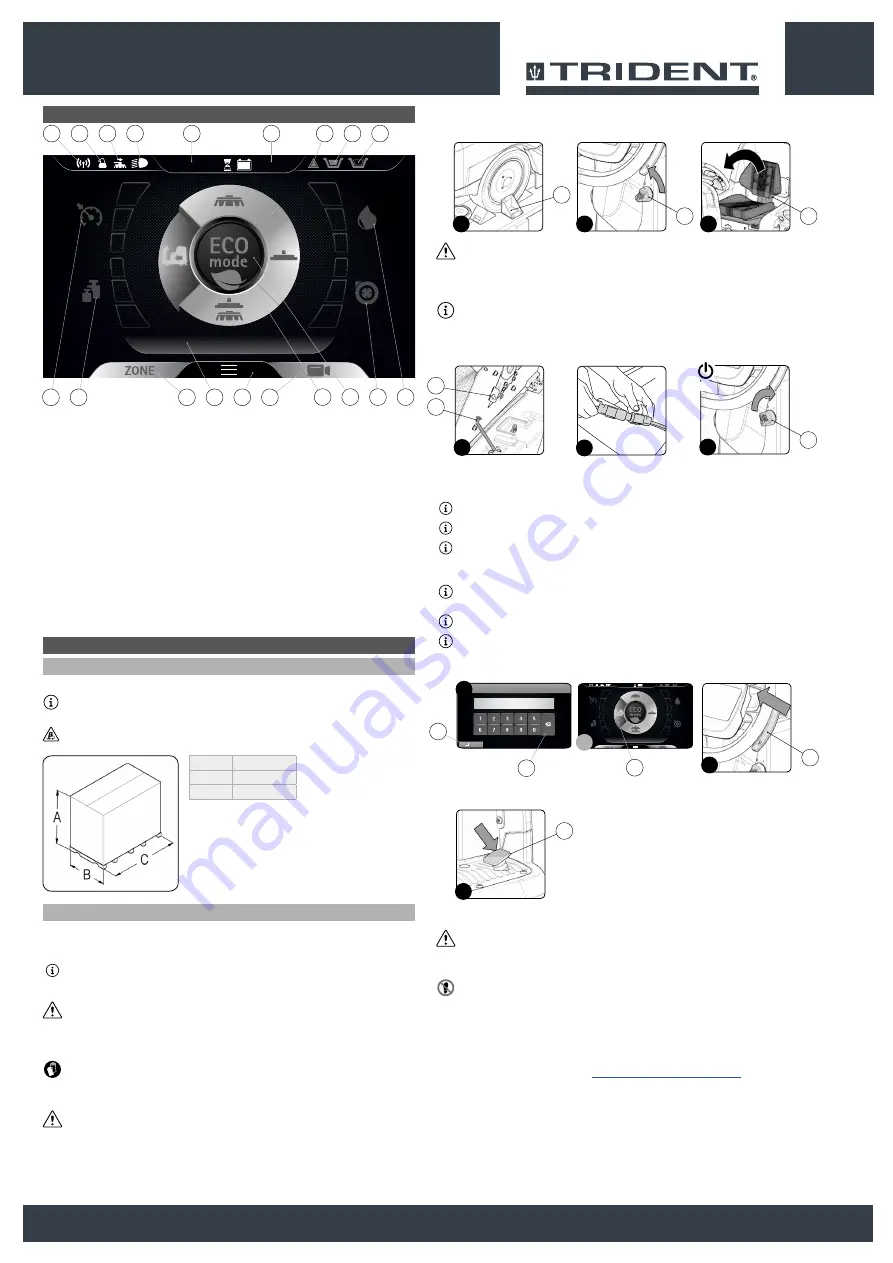
HOW TO UNPACK THE MACHINE
The machine is shipped in specific packaging. To remove it, proceed as follows:
1.
Place the lower part of the outer packaging in contact with the floor.
N.B.
: use the pictograms printed on the box as a reference.
2. Remove the outer package.
WARNING
: the machine is contained in specific packaging materials, whose elements (plastic
bags, staples, etc.) can pose potential hazards, and must not be left within reach of children,
disabled persons, etc.
3. Remove the boxes containing the disc brushes and squeegee body from the machine.
CAUTION
: these operations must be carried out using protective gloves to avoid any possible
contact with the edges or tips of metal objects.
4. At the rear of the machine position the three ramps present in the package.
ATTENTION
: the three ramps should be positioned so they are centred with the wheels of the
machine, so that the machine is not damaged during its descent.
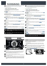
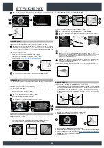
5.
The machine is fixed to the pallet with wedges (1) that block the wheels (
Fig.1
). Remove these
wedges.
6. Check that the main switch on the control panel has been set to “0”. If this is not the case, turn
the key (2) a quarter turn anti-clockwise (
Fig.2
). Remove the key from the main switch.
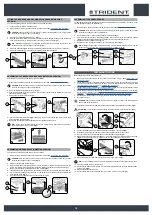
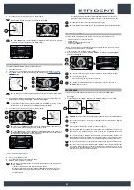
7. Grip the back of the seat (3) and turn the seat support plate to its maintenance position (
Fig.3
).
ATTENTION
: to prevent the seat from rotating, insert the retainer (4) into the slot (5) (
Fig.4
).
8. Connect the backup battery carriage's connector to the machine's main system connector
(
Fig.5
).
9. Grip the back of the seat (3) and turn the seat support plate to the working position.
N.B.
: before rotating the seat support plate, remove the retainer (4).
10. Sit on the driver’s seat.
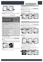
11. Insert the key (2) into the main switch on the control panel. Set the main switch to “I”, turn the key
a quarter turn clockwise (
Fig.6
).
12. A few seconds after ignition the password screen is displayed (
Fig.7
).
13. Enter the password and press the enter key (6) (
Fig. 7
).
N.B.
: to delete a wrong entry press the delete key (7) (
Fig. 7
).
N.B.
: it is possible to disable the password entry, contact the nearest assistance centre.
N.B.
: to find out the password to enter, contact the nearest assistance centre.
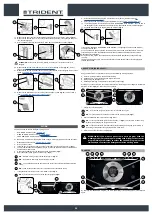
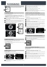
14. By default the machine is set to the transfer program (8) (
Fig. 8
).
NB
: in transfer mode both the brush head and the squeegee support will be in the resting
position (raised from the pallet).
NB
: in the DS selector the symbol of the transport program (8) is green (
Fig. 8
).
NB
: the grey symbols show working programs that are not active. the green symbols show
working programs that are active.
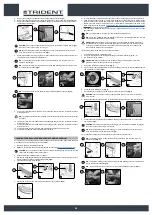
15. Engage reverse gear using the reverse gear activation/deactivation lever (9) (
Fig.9
).
16. Press the drive pedal (10) (
Fig.10
) to begin moving the machine.
17. Drive the machine down the ramp.
ATTENTION
: during this operation, check there are no people or objects near the machine.
18. Set the main machine switch to “0” (
Fig.2
). Remove the key from the main switch.
19.
Get off the machine.
CAUTION
: when getting down from the machine, do not place your foot on the scrubbing brush
head or side brush head brush.
20. Grip the back of the seat (3) and turn the seat support plate to the maintenance position.
21. Grip the handle (4) and lift the recovery tank to its maintenance position.
22. Disconnect the backup battery carriage connector from the main machine system connector.
23. Grip the handle (4) and lower the recovery tank to its working position.
24. Grip the back of the seat (3) and turn the seat support plate to the working position.
25.
For reasons of packaging, the brushes are supplied not fitted on the machine, to fit them to the
brush head body read the paragraph “
FITTING THE BRUSH HEAD BRUSHES
”.
2
3
1
1
2
3
6
2
ON
4
4
5
5
Enter
Inserire codice
DRIVE
0000.00
100%
7
8
7
6
8
9
9
10
10
15