background image

5.3.1

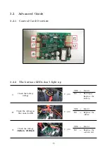
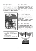
Control Card

The Main Card is the heart of the ma-
chine and, depending of the input infor-
mation, decides how to use the devices
of the machine during normal work. On
the table here below, is possible to iden-
tify the input/output signals of the card.

Input & Output Signals

J1

Brush motor, Suction motor and Water
Pump.

J2

Card power supply.

J5

Main Switch, Park Microswitch, LED
Light.

J6

Water Pump Switch.

5.3.2

Main Switch

The machine is provided with a main
switch positioned on the rear left corner,
which can be comfortably activated by a
pedal.
The activation is confirmed by lighting
up an LED located under the pedal.

5.3.3

Water Pump Switch

The machine is provided with a water
pump switch positioned on the rear right
corner, which can be comfortably acti-
vated by a pedal.
The activation is confirmed by lighting
up an LED located under the pedal.

5.3.4

Park Microswitch

The machine is provided with a park mi-
croswitch positioned at the base of the
articulated joint, which is activated by
moving the handle in any position.
With handle in vertical position, all func-
tions of the machine are inhibited.

5.3.4-1

5.3.4-2

5.3.4-3

27

Summary of Contents for TRIDENT NM14

Page 1: ...SERVICE MANUAL TRIDENT NM14 Version AA Date October 3 2017 Document Number 10056159...

Page 2: ...ctrical Installation 18 4 2 Mechanical Friction System 19 4 3 Drying System 21 4 4 Frame and Traction System 22 4 5 Solution Delivery System 23 III Machine Description 24 5 Electrical System 25 5 1 St...

Page 3: ...8 2 Description 34 8 3 Maintenance and Checks 34 9 Cleaning Solution Supply System 35 9 1 Structure 35 9 2 Description 35 9 3 Maintenance and Checks 36 10 Consumable Recommended Spare Parts 37 10 1Con...

Page 4: ...Part I Product Introduction 4...

Page 5: ...t is sufficient to remove the battery The Serial Number is an extremely important information which has to be provided each time a Technical Support is required or is necessary to buy spare parts or a...

Page 6: ...9 7 Maximum Ramp Gradient 2 Total Power W 150 Squeegee Width in 15 4 Solution Tank gal 0 31 Recovery Tank gal 0 26 Vacuum Motor Stages Depression Nr mBar 1 45 1 Vacuum Motor Voltage Power V W 24 100 M...

Page 7: ...AL DESCRIPTION U M NM14 Machine Weight Machine Brush Squeegee lb 20 Gross Weight of the machine in work conditions Machine Battery Water Brush Squeegee lb 25 1 Weight and Pressures depends on how much...

Page 8: ...Part II Anomalies Resolution Guide 8...

Page 9: ...ut the buttons LEDs do not light up Refer to the Advanced Guide see section 3 2 2 at page 13 The battery doesn t work properly 1 The battery is not properly con nected Insert the battery until the end...

Page 10: ...ctivate the Green LED power supply Ensure the mains plug is properly in serted into the charger If the problem persists replace the battery charger 4 The battery charger plugged in and turned on with...

Page 11: ...ith a proper one 8 The solution flow rate is not correct or not enough Refer to the proper section see section 3 1 3 at page 11 3 1 3 Solution delivery system what to do if The delivered solution is n...

Page 12: ...ee rubber blades are worn out or broken Rotate or replace the squeegee rub ber blades see section 7 3 1 at page 32 7 The squeegee vacuum chamber or the adapter is stuck or dirty Clean the squeegee 8 T...

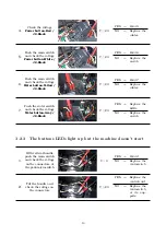
Page 13: ...ns LEDs don t light up 1 Check the battery voltage V 23 YES Point 2 NO Recharge Replace the battery 2 Check the voltage on the connector J2 V 23 YES Point 3 NO Replace the cables 3 Check the voltage J...

Page 14: ...Replace the cables 7 Push the water switch and check the voltage Water button Gray J2 Black V 23 YES Replace the LEDs NO Replace the switch 3 2 3 The buttons LEDs light up but the machine doesn t star...

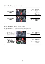
Page 15: ...ES Battery OK NO Replace the battery 3 2 5 The brush Motor doesn t work All the other devices of the machine are functioning properly 1 Check the voltage on the connector with running machine V 23 YES...

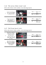
Page 16: ...ning machine V 23 YES Replace the cables NO Replace the control card 3 2 7 The Pump doesn t work All the other devices of the machine are functioning properly 1 Check the voltage in AC on the Pump s c...

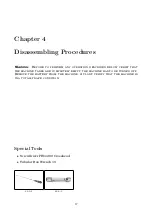
Page 17: ...RIBED BELOW VERIFY THAT THE MACHINE TANKS ARE COMPLETELY EMPTY THE MACHINE HAS TO BE TURNED OFF REMOVE THE BATTERY FROM THE MACHINE AT LAST VERIFY THAT THE MACHINE IS IN A TOTALLY SAFE CONDITION Speci...

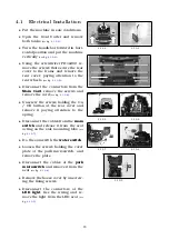
Page 18: ...4 1 0 6 Unscrew the screws holding the On Off button at the rear cover and remove it paying attention to the spring Disconnect the cables from the main switch and release it from the seat acting on t...

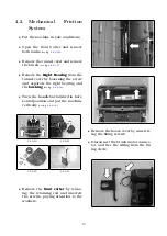
Page 19: ...rew and separate the right bearing and the bushing see fig 4 2 0 12 Turn the handlebar forward in hori zontal position and put the machine vertically see fig 4 2 0 13 4 2 0 10 4 2 0 11 4 2 0 12 4 2 0...

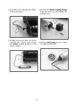
Page 20: ...19 Holding the motor with one hand unscrew the screw and remove the motor paying attention to the square washer Remove the brush coupling Flange from the motor by unscrewing the fixing screw Pull the...

Page 21: ...squeegee by rotating and pulling the side knobs see fig 4 3 0 17 Free the squeegee body from the squeegee holder by releasing the fix ing knobs see fig 4 3 0 18 see fig 4 3 0 19 Remove the wheels to...

Page 22: ...nt Carter and remove both tanks Unscrew the screw and remove the handle rod Remove the wheel cover hub by pressing with a screwdriver through the holes from the inner side of the wheel Unscrew the whe...

Page 23: ...r Filter 4 5 0 22 Place the machine vertically and re move the pump s protective carter by unscrewing the screws Disconnect the cables and hoses and remove the pump from the rub ber slots Reposition t...

Page 24: ...Part III Machine Description 24...

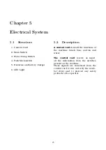
Page 25: ...LED Light 5 2 Description A control card runs all the functions of the machine brush base suction and water The control card receive as input all the information from the switches present on the machi...

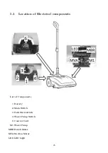
Page 26: ...5 3 Location of Electrical components List of Components 1 Battery 2 Main Switch 3 Park Microswitch 4 Water Pump Switch 6 Control Card M1 Water Pump MBR Brush Motor MVA Suction Motor LED LED Light 26...

Page 27: ...ositioned on the rear left corner which can be comfortably activated by a pedal The activation is confirmed by lighting up an LED located under the pedal 5 3 3 Water Pump Switch The machine is provide...

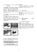
Page 28: ...5 3 5 5 5 3 5 6 5 3 5 7 A correct Charging cycle follows the be low series of illumination stages of the LED of the battery charger Phase LED Description 1 Red Battery charging 2 Green Battery charge...

Page 29: ...ing which consists in a device which rubs on the floor This device in this case a cylindrical brush has the function to mechanically remove the dirt from the ground and facilitate the reaction between...

Page 30: ...od condition and clean In case of excessive wear it is necessary to proceed with the replacement Maintenance to perform every 600h Bearings replacement Refer to Disassembling Chapter see section 4 2 a...

Page 31: ...t out from the floor The system is basically made by a vacuum motor which produces an un derpressure in the system This underpressure causes an air flow which flows in the whole vacuum sys tem The air...

Page 32: ...both sides before having to be re placed Proceed at reverse to reassemble the squeegee body correctly Maintenance to perform every 150h Replacing Squeegee Wheels Put the machine in safe conditions Pl...

Page 33: ...le A and from the output one B Successively with compressed Air clean the air conveyor compartment of the suction motor C D 7 3 5 Recovery Tank Check to perform every 50h The recovery tank has to be c...

Page 34: ...y the mechanical friction system The wheels are directly fixed to the frame 8 3 Maintenance and Checks 8 3 1 Wheels Check to perform every 50h The wheel must be free to rotate smoothly without frictio...

Page 35: ...hine will use to clean The solution is then canalized to the filter which in addition to allowing the valve opening of the solution tank stops debris that could stuck the hoses system and compromise t...

Page 36: ...t used with the machine If necessary proceed with the replacement of the damaged hoses 9 3 3 Clean Water Filter Check to perform every 2h The filter is of great importance since due to its knob it all...

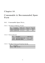
Page 37: ...ion Width in Bristle in Bristle type 440904 MAIN BROOM 13 4 4 3 0 012 PPL 440905 MAIN BROOM 13 4 4 3 0 012 PPL 10 1 2 Drying System PN Description Dimensions 224800 SQUEEGEE RUBBER KIT 15 8 x 1 x 0 08...

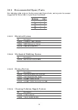
Page 38: ...ion 439802 CONTROL CARD CFSS000 439524 SWITCH General Water 441658 PARK MICROSWITCH 10 2 2 Mechanical Rubbing System PN Description 224760 MOTOR 24V 32W 375RPM 10 2 3 Drying System PN Description 2246...

Page 39: ...Hillyard Inc Service Manual TRIDENT NM14 Hillyard Inc 302 North 4th Street P O Box 909 St Joseph Missouri 64501 USA Tel 1 800 365 1555 Fax 1 800 881 3840 Edition October 3 2017...

Reviews: