Instruction manual
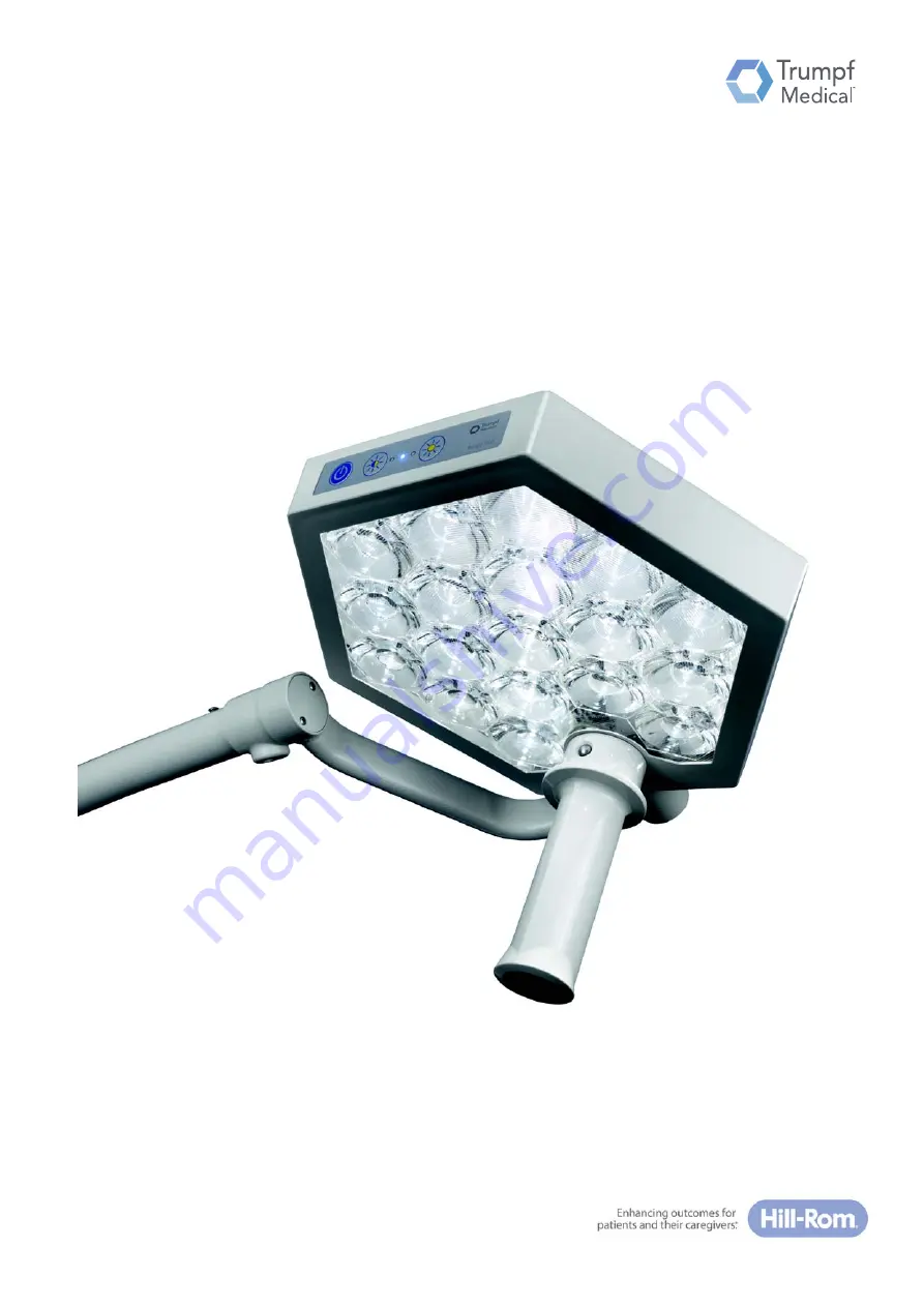
TruLight™ 1000 examination light
Read the instruction manual before using the product and store for later reference.
Englishen-EN
Page 1: ...Instruction manual TruLight 1000 examination light Read the instruction manual before using the product and store for later reference English en EN...
Page 2: ...55000 00012_002_01 1695233 25 01 2018 2...
Page 3: ...ns and requirements regarding the operation and care of the device This instruction manual applies to the following components Device versions TruLight 1000 lighting system Version with light head as...
Page 4: ...l will hereinafter be used as a synonym for TRUMPF Medizin Systeme GmbH Co KG to improve readability Technical Customer Service The contact data for the current sites of the technical customer service...
Page 5: ...n writing by TRUMPF Medizin Systeme GmbH Co KG hereinafter referred to as Trumpf Medical Trumpf Medical will assume no liability whatsoever arising from or connected with the use of unapproved informa...
Page 6: ...Proper use 13 1 7 4 Special features 13 1 7 5 Improper use 13 1 8 Ambient conditions for operation and storage 13 1 8 1 Ambient conditions for operation 14 1 8 2 Ambient conditions for storage 14 1 9...
Page 7: ...rules 35 7 2 Preparatory measures 35 7 3 Measures to take when using the lighting system 36 7 4 Attaching removing the sterilisable handle 37 7 5 Positioning the light head 37 7 6 Switching the light...
Page 8: ...Table of contents 8 55000 00012_002_01 1695233 25 01 2018 12 Wearing parts 50 13 Troubleshooting 51 14 Technical data 52 14 1 Device data 52 14 2 EMC information 53...
Page 9: ...used The operator is obliged to provide a safe device and appropriately instruct the user regarding operation and proper use of the device 1 3 2 User Users are individuals who by their qualifications...
Page 10: ...nformation at any time Never hand the device to third parties without the valid instruction manual Ensure that the instruction manual provided with the device is valid by checking the identity and ver...
Page 11: ...Japan The mains connection wiring may only be used with the equipment supplied 1 5 1 Transportation damage Damage claims Claims for damage cannot be accepted unless Trumpf Medical is notified without...
Page 12: ...1 7 Conformity 1 7 1 Identification Conformity The manufacturer declares that this product conforms to the fundamental requirements according to MDD Appendix I and documents this by means of the CE an...
Page 13: ...ield of vision For examinations in the facial area with unprotected and open eyes high levels of local light intensities may lead to damage to eyesight The patient s eyes must be closed or protected a...
Page 14: ...performed as specified in IEC 60601 1 and IEC 60601 1 1 or in accordance with the specifications provided by the manufacturer Compliance with this standard must be ensured by the service technician r...
Page 15: ...NTION indicates a potentially dangerous situation which unless avoided can lead to damage to property 2 1 3 Indicating additional information NOTE provides you with additional information and helpful...
Page 16: ...uctions Location requirements Gas explosion The lighting system is not suitable for use in an environment in which flammable mixtures of anaesthetics with oxygen or laughing gas in a high concentratio...
Page 17: ...ination of the light head Electrostatic charge balance Complications due to electrostatic discharge To avoid complications due to electrostatic discharge between parts of the device and patients the u...
Page 18: ...the wipe over method only for disinfection To clean or disinfect the device the cloth for wiping must be moist and not wet Dispense cleaning agents and disinfectants so that no liquid can enter throu...
Page 19: ...or a person with equivalent qualification Deinstallation for service purposes The spring arm may bounce up If the light head is removed without first moving the spring arm to the highest limit positio...
Page 20: ...with LED light sources Service life LEDs have a very long service life unlike conventional halogen or discharge lights Low heat generation Further advantages of the LEDs are that they generate less he...
Page 21: ...bers 2 identify the individual components of a device 4 1 1 Markings on the ceiling mounted version A Ceiling mounted version The device label 1 with the main serial number on the ceiling conduit Seri...
Page 22: ...2 Figure 2 4 1 3 Markings on the mobile stand version C Mobile stand version Device label with the main serial number on the cover of the power supply unit Serial numbers of the individual components...
Page 23: ...h the horizontal rota ng boom The horizontally and vertically adjustable spring arm Power supply Under the canopy there is the ceiling fastening and the components for the power supply to the light sy...
Page 24: ...tal rotation movement 360 Spring arm on the boom hinge B Full horizontal rotation movement 360 Vertical swivel movement in the range 35 to 45 Quarter bracket on the spring arm hinge A Full vertical ro...
Page 25: ...ng arm Power supply The power to the wall mounted version can be supplied by three types of connection A Power supply box with xed connec on 100 V 240 V B Power supply box fed by a mains cable with co...
Page 26: ...ntal rotation movement 180 Spring arm on the boom hinge B Full horizontal rotation movement 360 Vertical swivel movement in the range 35 to 45 Quarter bracket on spring arm hinge A Full vertical rotat...
Page 27: ...ustable spring arm Power supply The power supply to the stand version is established at the power supply unit with The mains cable with cold device plug for connection to the cold device socket on the...
Page 28: ...on stand rod hinge B Horizontal rotation movement in the range 30 to 30 Vertical swivel movement in the range 35 to 45 Quarter bracket on spring arm hinge A Full vertical rotation movement 360 Light...
Page 29: ...the event of contact with damaged electrical components of the wall mounted mobile stand version Do not connect the lighting system to the mains in the event of defective plug connectors or or damage...
Page 30: ...et and the light head when rota ng the light head Only position the light head with the sterilisable handle 6 1 2 Risks of collision during positioning The lighting system has an impact proof surface...
Page 31: ...g the sterilisable handle position the light head at a working distance of 70 150 cm from the area of the patient which is to be examined Examinations in the field of vision Damage to vision In case o...
Page 32: ...system 1 Check the cold device plug the mains plug and the mains cable for damage 2 Route mains cable from power supply box so that no tension forces are able to affect the cable Electric shock In cas...
Page 33: ...ket and roll up the mains cable on the stand handle to move the stand The stand might lt when the castors are locked and excessive force is exerted onto the spring arm or light head Avoid strong lever...
Page 34: ...the mains plug and the mains cable for damage 2 Lay the mains cable so that there is no danger of tripping and so that there is no strain on the cable 3 Check whether the mains voltage corresponds to...
Page 35: ...in particular on the cover plates of the light head and the sterilisable handle Secure mounting of the sterilisable handle Electric shock There is a risk of electric shock in the event of contact with...
Page 36: ...light 7 3 Measures to take when using the lighting system Measures that should be considered while using the lighting system Strong light fields Damage to patient s tissue High levels of illumination...
Page 37: ...e light head is only possible with the handle attached For medical purposes only use light heads with the handle attached Putting on the sterilisable handle Push the sterilisable handle onto the handl...
Page 38: ...ess the ON OFF bu on on the control panel The light head goes out Disconnecting the voltage supply Ceiling and wall mounted version with fixed connection Switch off the operating theatre master switch...
Page 39: ...nts or openings of the surgical lamp or parts of the support arm system Use the surface disinfectant only at the concentration specified by the manufacturer Only use disinfectants approved by the manu...
Page 40: ...n or steaming is not permissible Warranty claim Failure to comply with cleaning or disinfection requirements will render any warranty claim void No warranty is accepted for damage which is due to the...
Page 41: ...n whilst disinfection is in progress After wipe over disinfection wait until the disinfectant has completely dried Ensure the room is adequately ventilated Comply with national guidelines The operator...
Page 42: ...le is dirtied or the cover panel is scratched 9 2 Cleaning and disinfection Sterilisation faults lead to product damage Product damage may result when the specifications and instructions provided belo...
Page 43: ...e and temperature values can in principle be used for machine based cleaning 9 3 Sterilising handles for examination lights Material The handles are made of heat and impact resistant polyphenylene sul...
Page 44: ...nge damaged handles 6 Check the cover pane where present for firm attachment and exchange the handle as required An automatic method using a machine disinfector should be used for cleaning disinfectio...
Page 45: ...on The sterilisation packaging must be large enough for the handle so that the seal is not under tension The maximum load of the steriliser may not be exceeded when several handles are sterilised in o...
Page 46: ...handle Secure mounting of the sterilisable handle Defective devices Defective devices or functional units must be clearly labelled immediately and taken out of operation Inform the technical customer...
Page 47: ...edical equipment According to the MPBetreibV the performance of safety inspections as well as service and maintenance work must be documented in a medical product logbook This medical product logbook...
Page 48: ...efully lever o the cover cap from the joint of the spring arm using a thin blade 2 Swivel the spring arm to the top end posi on 35 Uncontrolled rotation of the spring arm Risk of injury due to uncontr...
Page 49: ...int between the spring arm and the quarter bracket The fric on brake of the quarter bracket acts through the friction force of the adjustment screw slot head screw on the quarter bracket pin 1 Adjust...
Page 50: ...perating company following appropriate hospital technician training by Trumpf Medical Handles and brake screws High wear part Chapter Sterilisable handle for light head plastic pack of 3 see Chapter 7...
Page 51: ...ght head is outside the working area Position the light head see Chapter 7 7 The light does not light up Main switch in the examination room is switched off Switch on the main switch see Chapter 7 6 L...
Page 52: ...e span 50 000 hrs Classification according to MPG Safety class I Mode of operation Suitable for continuous operation Designation Technical data for the lighting sys Central lighting intensity at a def...
Page 53: ...o or on top of other devices WARNING NOTE NOTE Guidelines and manufacturer s declaration electromagnetic immunity TruLight 1000 is intended for use in the ELECTROMAGNETIC ENVIRONMENT described below T...
Page 54: ...ables 100 kHz repetition rate Mains power quality should be that of a typical commercial or hospital environment Surges according to EN IEC 61000 4 5 1 kV outer conductor outer conductor voltage 2 kV...
Page 55: ...nment NOTE Immunity test EN IEC 60601 1 test level Compliance level Conducted RF interference variables according to EN IEC 61000 4 6 3 V 0 15 MHz 80 MHz 6 V in the ISM band and amateur radio bands be...
Page 56: ...460 Pulse modulation FM 5 kHz variation 1 kHz sine 2 0 3 28 710 704 787 LTE band 13 17 Pulse modulation 217 Hz 0 2 0 3 9 745 780 810 800 960 GSM 800 900 TETRA 800 iDEN 820 CDMA 850 LTE band 5 Pulse m...
Page 57: ...communication equipment Nominal power of the transmitter W Safe distance according to transmission frequency m 150 kHz to 80 MHz d 1 2 P 80 MHz to 800 MHz d 1 2 P 800 MHz to 2 5 GHz d 2 3 P 0 01 0 1...
Page 58: ...F Medizin Systeme GmbH Co KG Carl Zeiss Stra e 7 9 D 07318 Saalfeld Telefon 49 3671 586 0 Telefax 49 3671 586 41165 E Mail info trumpfmedical com www trumpfmedical com 55000 00012_002_01 1695233 25 01...