


20
USE
AND
MAINTENANCE
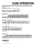
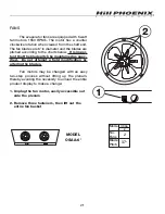
CASE CLEANING
Case is designed to facilitate cleaning. There is a wide
radius formed on the front and back of the inside bottom
that helps accelerate liquid flow and eliminates difficult-to-
clean sharp corners. All surfaces pitch to a deep-drawn
drain trough that angles toward the front and center of case
where the waste outlet is located for easy access.
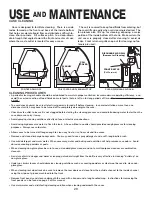
The coil is covered to keep food fluids from entering, but
the cover lifts up easily when coil cleaning is desired. The
fan plenum also lifts up for cleaning, exposing a major
portion of the inside bottom of the tank. Make certain the
coil cover is properly closed after cleaning to avoid air
leaks. Front return air grills snap out for cleaning; no fas-
teners are used.
COIL COVER AND PLENUM LIFT UP
POSITIVE DRAIN OFF
CLEAN DISCHARGE AIR GRILL
DISCHARGE AIR GRILL
(Remove for Cleaning)
FRONT BAFFLE
(Pull Forward)
PLENUM
COIL
COIL
COVER
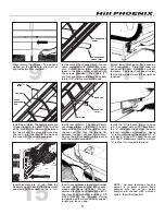
CLEANING PROCEDURES
• A periodic cleaning schedule should be established to maintain proper sanitation, insure maximum operating efficiency, and
avoid the corrosive action of food fluids on metal parts that are left on for long periods of time. We recommend cleaning once
a week.
• To avoid shock hazard, be sure all electrical power is turned off before cleaning. In some installations, more than one
disconnect switch may have to be turned off to completely de-energize the case.
• Check waste outlet to insure it is not clogged before starting the cleaning process and avoid introducing water faster than the
case drain can carry it away.
• Avoid spraying cleaning solutions directly on fans or electrical connections.
• Avoid using high pressure water to flush the tank. A hose without a nozzle should provide enough pressure for cleaning
purposes. Always use cold water.
• Allow cases to be turned off long enough to clean any frost or ice from coil and flue areas.
• Remove and clean discharge honeycomb. You may need to use spray detergent and a soft, long bristle brush.
• Use mild detergent and warm water. When necessary, water and baking soda solution will help remove case odors. Avoid
abrasive scouring powders or pads.
• When cleaning non-glare glass be sure to use a standard glass cleaner and not a multi-purpose cleanser or combination
cleanser.
• A mixture of white vinegar and water or isopropyl alcohol straight from the bottle is very effective in cleaning “build-up” on
non-glare glass.
• Under no circumstances should abrasive cleaning solutions such as scouring powders or steel wool be used to clean non-
glare glass.
• When cleaning rear door tracks be sure to remove the rear doors and clean from the outside channel to the inside channel
using the wipe-out groove machined into the track.
• Remove front panels and clean underneath the case with a broom and a long handled mop. Instructions for removing the
front panels can be found on page 9 of this manual.
• Use warm water and a disinfecting cleaning solution when cleaning underneath the cases.
Summary of Contents for Origin2 OSAA
Page 1: ...DELI C A S E S MODEL OSAA HANDBOOK INSTALLATION OPERATION 9 03 P061773M...
Page 2: ......
Page 4: ......
Page 29: ...25 NOTES...
Page 30: ...26 NOTES...