9
9
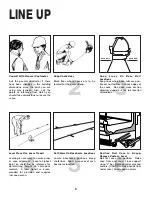
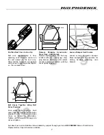
Close joints of front panel. The panel is
slotted on the bottom to allow left or
right adjustment as required.
10
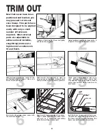
Install curved front panel joint (if cases
come equipped with curved front pan-
els). Curved panel joints are shipped
loose in the case and are attached with
the screws provided. Wide joints (1”)
are for case-to-case joining and narrow
joints (1/2”) are for cases with ends.
11
Attach lower front panel (for cases on
11” baseframes). Slots and tabs are
designed for easy installation without
fasteners. The lower front panel is slot-
ted to allow adjustment left or right as
required.
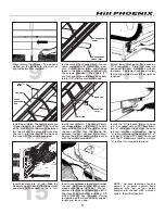
12
Install top sill joint. The top sill joints are
shipped loose in the case. The front lip
of the joint fits into the crevice between
the top sill and the glass pressure bar.
The rear lip is attached to the back of
the case with the screws provided.
13
Install rear sill joint. The rear sill joints
are shipped loose in the case. The bot-
tom portion of the joint should be slid on
the rear sill first then the top lip fits
between the rear sill and the mullion.
Secure the joint underneath the rear sill
with the screws provided.
14
Install the “J” rail onto the case base
rail. For cases with an 11” baseframe,
the “J” rail easily slides over the base
rail and requires no fasteners. Space
“J” rails evenly along the base rail (2 “J”
rails per 6’, 8’, and 12’ case). For cases
with the 7” baseframe there is a single
“J” rail that is screwed into place.
15
Insert kickplate into “J” rail. Slide the
kickplate up and behind the lower front
panel bracket then down on the “J” rail.
NOTE: An easy technique for one
person is to press against nose
bumper with leg as you guide
bumper into channel with a screen
spline. Insert bottom first.
CURVED FRONT
PANEL JOINT
CURVED FRONT
PANEL
TOP SILL
JOINT
TOP SILL
GLASS
PRESSURE
BAR
REAR SILL
JOINT
REAR SILL
MULLION
16
Insert nose bumper into master bumper
channel. Roll nose bumper into channel
along entire lineup (up to 96’). We rec-
ommend that the nose bumper be left in
the store 24 hours before installing. DO
NOT STRETCH the bumper during
installation as it will shrink to its original
length and leave a gap.
Summary of Contents for Origin2 OSAA
Page 1: ...DELI C A S E S MODEL OSAA HANDBOOK INSTALLATION OPERATION 9 03 P061773M...
Page 2: ......
Page 4: ......
Page 29: ...25 NOTES...
Page 30: ...26 NOTES...

