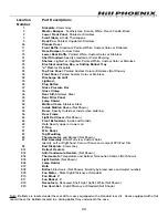


15
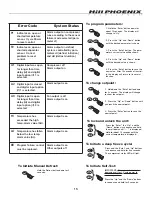
Error Code
System Status
F2
Indicates an open or
shorted evaporator
sensor. Correct
problem to reset
control.
}
}
}
F1
Indicates an open or
shorted temperature
sensor. Cycle Power
to reset control.
A2
Digital input is closed
and digital input option
(if) 1 is selected.
A3
Digital input is open
for longer than time
delay (id) and digital
input option (if) 3 is
selected.
HI
Temperature has
exceeded the high
temp. alarm value (AH).
LO
Temperature has fallen
below the low temp.
alarm value (AL).
EE
Program failure: control
must be replaced.
A1
Digital input was open
for longer than time
delay (id) and digital
input option (if) 1 is
selected.
Alarm output on defrost
cycle is controlled by para-
meters di (defrost initiation)
and dd (defrost duration)
Alarm output on compressor
runs according to the sensor
failure mode selected (para-
meter sf)
Alarm output is on
Fan output is off
Alarm output is on
Alarm output is on
Alarm output is on
Alarm output is on
Other outputs off
Compressor off
Alarm output on
IMPORTANT: Disconnect loads before
beginning self test. Cycle power to
resume operation.
Press the “Up” and the “Down” buttons
in sequence and hold for 5 seconds.
To Initiate Self-Test:
Press and the “Enter” and “Up” buttons
in sequence and hold for five seconds.
The compressor status LED will light.
To Initiate a deep freeze cycle:
Press the “Enter,” the “Up,” and the
“Down” buttons in sequence and hold
them all down until “- - -” is displayed.
Hold for about 10 seconds until the
current temperature is displayed.
To lock and unlock the unit:
1. Hold down the “Enter” button down
for 3 seconds. The display will change
to show the setpoint.
2. Press the “Up” or “Down” button until
you reach the new setpoint.
3. Press the “Enter” button to save the
new setpoint.
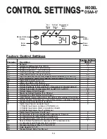
To change setpoint:
1. Hold the “Enter” button down for
about 10 seconds. The display will
change to “Hy.”
2. Press the “Up” and “Down” button
until the desired parameter is shown
3. Press the “Enter” button. The para-
meter’s current value will be shown.
4. Press the “Up” and “Down” button
until the desired value is shown.
5. Press the “Enter” button to save the
new value. After 10 seconds of inactivi-
ty, the display will return to its normal
function.
To program parameters:
Hold the Defrost button down for 3
seconds.
To Initiate Manual Defrost:
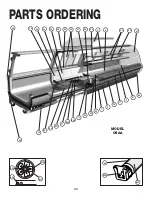
Summary of Contents for Origin2 OSAA
Page 1: ...DELI C A S E S MODEL OSAA HANDBOOK INSTALLATION OPERATION 9 03 P061773M...
Page 2: ......
Page 4: ......
Page 29: ...25 NOTES...
Page 30: ...26 NOTES...