Video Intercom Door Station
·
User Manual
31
2.
Set the negative floor.
3.
Select the interface type: RS-485 or Network Interface.
If you select RS-485, please make sure you have connected the door station to the
elevator controller with RS-485 wire.
If you select Network Interface, please enter the elevator controller’s IP address, port
No., user name, and password.
4.
Enable the elevator control.
Up to 4 elevator controllers can be connected to one door station.
Up to 10 negative floors can be added.
Make sure the interface types of elevator controllers, which are connected to the
same door station, are consistent.
IO Input and Output
Step:
1.
Click the
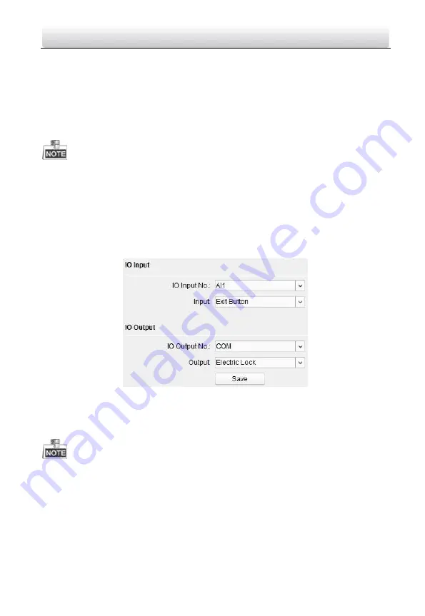
I/O Input and Output
button to enter the I/O input and output interface.
Figure 7-25
IO Input/Output Configuration
2.
Select I/O input No., input mode, output No., and output mode.
3.
Click the
Save
button to enable the settings.
For door station (V series), there are 4 I/O Input Terminals, corresponding to
SENSOR
interfaces (S1, S2, S3, S4) of door station.
For door station (D series and V series), there are 4 I/O Output Terminals.
Terminal 1~2 correspond to
DOOR
interfaces (NO1/COM1/NC1; NO2/COM2/NC2)
of door station. You can enable/disable IO Out by selecting from the dropdown list.
Terminal 3~4 correspond to interfaces of
ALARM OUT
(AO1+, AO1-; AO2+, AO2-).


