background image

DS-A83 Series ICVS Quick Start Guide 

14 


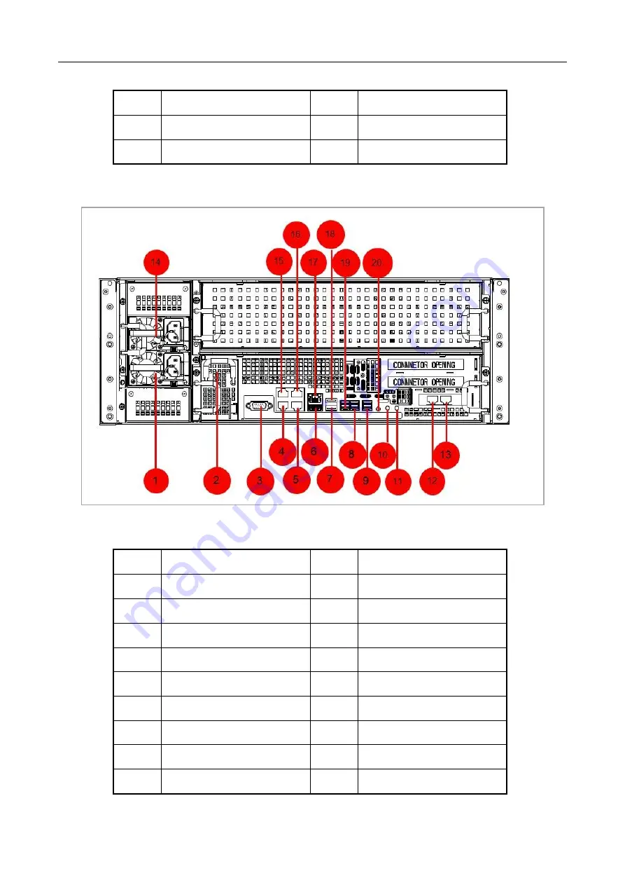
2.3.3 DS-A83024S-ICVS and DS-A83024S-ICVS/Micro 


Figure 2-8


Rear Panel 

Table 2-4


Rear Panel Description 

LAN 1 & LAN 3 

12 

LAN 5 

LAN 2 & LAN 4 

16 

LAN 6 

SAS interface 


No. 

Name 

No. 

Name 

Power module 1 

11 

Power switch 

BBU (optional) 

12 

LAN 5 

RS-232 interface 

13 

LAN 6 

LAN 1 

14 

Power module 2 

LAN 2 

15 

LAN 3 

USB interface 1 

16 

LAN 4 

USB interface 2 

17 

Management LAN 

SAS interface 2 

18 

USB interface 3 

SAS interface 3 

19 

SAS interface 1 

Summary of Contents for DS-A81 Series

Page 1: ...0 DS A81 and DS A83 Series ICVS Quick Start Guide...

Page 2: ...Indicators on Front Panel 11 2 3 Rear Panel 12 2 3 1 DS A81024S ICVS and DS A81024S ICVS Micro 12 2 3 2 DS A81048S ICVS and DS A81048S ICVS Micro 13 2 3 3 DS A83024S ICVS and DS A83024S ICVS Micro 14...

Page 3: ...INCLUDING AMONG OTHERS DAMAGES FOR LOSS OF BUSINESS PROFITS BUSINESS INTERRUPTION OR LOSS OF DATA CORRUPTION OF SYSTEMS OR LOSS OF DOCUMENTATION WHETHER BASED ON BREACH OF CONTRACT TORT INCLUDING NEGL...

Page 4: ...ence 2 This device must accept any interference received including interference that may cause undesired operation EU Conformity Statement This product and if applicable the supplied accessories too a...

Page 5: ...cro DS A83048S ICVS Micro Symbol Conventions The symbols that may be found in this document are defined as follows Symbol Description Provides additional information to emphasize or supplement importa...

Page 6: ...he device turn off the power at once and unplug the power cable and then please contact the service center Preventive and Cautionary Tips Before connecting and operating your device please be advised...

Page 7: ...mended Grounding for DC power supply system the chassis must be properly grounded Connect all power cords before applying power to the redundant power supply module The storage system supports managem...

Page 8: ...o 80 RH Storage humidity 5 RH to 95 RH Transportation humidity 5 RH to 95 RH 1 2 Installation and Initial Power on The device shall be placed on the fixed flat surface Tilting surface is not allowed Y...

Page 9: ...e of alarm beeper produced during the system running please take immediate check and solution 1 4 Device Reliability To enhance the reliability of the operating of the device you can connect to the NT...

Page 10: ...iption 2 1 Overall View The device adopts rack chassis There are status indicators on the front panel You can view the system status via the indicators directly Figure 2 1 DS A81024S ICVS DS A83024S I...

Page 11: ...ICVS There are 24 HDD slots on the front panel for DS A83024S ICVS DS A81024S ICVS DS A81024S ICVS Micro DS A83024S ICVS Micro Digits in figure show the HDD sequence Figure 2 3 Front Panel 2 2 2 DS A...

Page 12: ...Buttons and Indicators on Front Panel Figure 2 5 Buttons and Indicators Table 2 1 Buttons and Indicators Description No Name Description 1 Power button When device is off press it to start device Whe...

Page 13: ...n starts stops flashing in blue after you press it or click the positioning button on configuration interface Then you press it again and it will be unlit 3 Mute Alarm button When an alarm occurs in d...

Page 14: ...13 2 3 2 DS A81048S ICVS and DS A81048S ICVS Micro Figure 2 7 Rear Panel Table 2 3 Rear Panel Description 7 SAS interface 8 COM No Name No Name 1 Power module 8 COM 2 VGA 9 Power switch 3 Management L...

Page 15: ...5 LAN 1 LAN 3 12 LAN 5 6 LAN 2 LAN 4 16 LAN 6 7 SAS interface No Name No Name 1 Power module 1 11 Power switch 2 BBU optional 12 LAN 5 3 RS 232 interface 13 LAN 6 4 LAN 1 14 Power module 2 5 LAN 2 15...

Page 16: ...A83048S ICVS Micro Figure 2 9 Rear Panel Table 2 5 Rear Panel Description 10 FN button 20 COM No Name No Name 1 Power module 1 12 LAN 5 2 BBU optional 13 LAN 6 3 RS 232 interface 14 Power module 2 4...

Page 17: ...DS A83 Series ICVS Quick Start Guide 16 7 USB interface 2 18 USB interface 3 8 SAS interface 2 19 SAS interface 1 9 SAS interface 3 20 COM 10 FN button 21 Power module 3 11 Power switch...

Page 18: ...not running Step 1 Place the device in an appropriate position and connect the peripheral devices 1 Connect the power cord to the socket firmly 2 Connect all the data network interfaces to layer 3 Gig...

Page 19: ...iver to remove the baffle in the bottom of dummy HDD Figure 3 2 Remove Baffle Step 5 Place the HDD in the dummy HDD The interface must face the dummy HDD rear Step 6 Adjust the HDD position Ensure the...

Page 20: ...e following instructions When fastening HDD on dummy HDD use the delivered screws to avoid too long screws damage HDD The device supports HDD hot plug You can hot plug HDD when device is on but this m...

Page 21: ...you start Connect all the data ports to Gigabit switch with the delivered CAT 5e cables Step 1 Check if the power supply is plugged into an electrical outlet It is HIGHLY recommended that an Uninterr...

Page 22: ...ur computer IP address Ensure it is in the same network segment with the Management LAN of the device the default IP address of Management LAN is 10 254 254 254 Step 1 Enter the device IP address http...

Page 23: ...sing Using a minimum of 8 characters including at least three of the following categories upper case letters lower case letters numbers and special characters in order to increase the security of your...

Page 24: ...Step 1 Go to Device Step 2 Click Information Overview Step 3 Click Modify Network Figure 6 1 Modify Network Step 4 Click Settings of a bound port Port Name Not editable Jumbo Frame Size Default value...

Page 25: ...DS A83 Series ICVS Quick Start Guide 24 Figure 6 2 Set Bound Port Management port does not support port binding Connect all bound ports to network...

Page 26: ...p 1 Go to Maintenance Time Management Figure 7 1 Time Management Step 2 Select Time Zone Step 3 Select Time Sync as Manual Time Sync Step 4 Click OK 7 2 Synchronize Time by NTP Step 1 Go to Maintenanc...

Page 27: ...DS A83 Series ICVS Quick Start Guide 26 Figure 7 2 NTP Time Sync...

Page 28: ...2 Specify search conditions Usage Unused Disk that not used by any RAID domain Single Disk Mode Reserved When disk Usage is set as Unused Status description is shown as follows Normal Disk is normal i...

Page 29: ...to show help You can follow the help to recover disk Step 4 Optional To locate a disk check the disk and click Locate to turn on FN indicator of the disk FN indicator will keep flashing default flashi...

Page 30: ...DS A83 Series ICVS Quick Start Guide 29 UD23482B...

Reviews: