background image

Chapter 4 Switch Configuration

4.1 Port Configuration

4.1.1 Attribute Configuration

The basic parameters can influence the working status of ports. Configure the parameters

according to the actual situation.
Steps

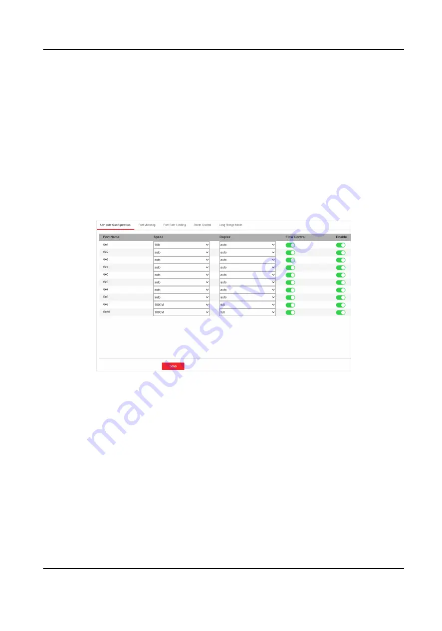
1. Go to Switch Configuration → Basic Configuration → Port Configuration → Attribute

Configuration .

Figure 4-1 Port Attribute Configuration

2. Configure the parameters.

Speed

The speed of data transmission of the port.
• PoE port: The default is auto.

• SFP fiber optical port: The default is auto that cannot be edited.

Duplex

The duplex mode of the port.
• PoE port: The default is auto that cannot be edited.

• SFP fiber optical port: The default is auto that cannot be edited.

Flow Control

Enabling the flow control can prevent data loss in data transmission.

Gigabit PoE Switch Web User Manual

7

Summary of Contents for DS-3E1510P

Page 1: ...Gigabit PoE Switch Web User Manual...

Page 2: ...ENT WILL HIKVISION BE LIABLE TO YOU FOR ANY SPECIAL CONSEQUENTIAL INCIDENTAL OR INDIRECT DAMAGES INCLUDING AMONG OTHERS DAMAGES FOR LOSS OF BUSINESS PROFITS BUSINESS INTERRUPTION OR LOSS OF DATA CORRU...

Page 3: ...IVITIES IN THE CONTEXT RELATED TO ANY NUCLEAR EXPLOSIVE OR UNSAFE NUCLEAR FUEL CYCLE OR IN SUPPORT OF HUMAN RIGHTS ABUSES IN THE EVENT OF ANY CONFLICTS BETWEEN THIS MANUAL AND THE APPLICABLE LAW THE L...

Page 4: ...cause harmful interference 2 This device must accept any interference received including interference that may cause undesired operation EU Conformity Statement This product and if applicable the supp...

Page 5: ...Industry Canada ICES 003 Compliance This device meets the CAN ICES 3 A NMB 3 A standards requirements Gigabit PoE Switch Web User Manual iv...

Page 6: ...nce degradation or unexpected results Note Provides additional information to emphasize or supplement important points of the main text Safety Instruction Danger This is a class A product and may caus...

Page 7: ...e leakage of flammable liquid or gas Dispose of used batteries according to the instructions Caution CAUTION Double pole Neutral fusing After operation of the fuse parts of the device that remain ener...

Page 8: ...ge Mode Configuration 11 4 2 Link Aggregation Configuration 12 4 3 VLAN Configuration 14 4 3 1 Add a VLAN 14 4 3 2 Configure a Port 15 4 4 QoS Configuration 16 4 5 SNMP Configuration 18 4 5 1 SNMP Pro...

Page 9: ...tion File Export 27 5 4 Configuration File Import 28 5 5 Device Upgrade 28 5 6 Log Management 28 5 7 Network Diagnostics 29 5 8 User Management 30 5 9 Security Management 31 Gigabit PoE Switch Web Use...

Page 10: ...ced PoE power supply technology and gigabit networks design on the basis of high performance access The switches support Web management and various layer 2 management protocols such as STP RSTP VLAN l...

Page 11: ...manual are for illustration purpose only 1 Enter the default IP 192 168 1 64 in the browser address bar Figure 2 1 Activation Note You are recommended to use the newest version of the following browse...

Page 12: ...2 Change the IP address mask address the gateway address DNS and alternative DNS as needed You can log in to the switch with the new IP address next time Note You are recommended to change the networ...

Page 13: ...ion working status port status port statistics and PoE status Device Information Figure 3 1 Device Information Management VLAN The management VLAN is VLAN 1 by default that cannot be edited MAC Addres...

Page 14: ...View the device running time memory usage and CPU usage Port Status Figure 3 3 Port Status View the connection status rate duplex and flow control of all ports Port Statistics Figure 3 4 Port Statist...

Page 15: ...hen you choose Manually Refresh you can click Refresh to refresh the statistics Reset You can click Reset to clear all the statistics PoE Status Figure 3 5 PoE Status View the complete appliance PoE s...

Page 16: ...nfiguration Figure 4 1 Port Attribute Configuration 2 Configure the parameters Speed The speed of data transmission of the port PoE port The default is auto SFP fiber optical port The default is auto...

Page 17: ...going packets from one port to a mirroring port Steps 1 Go to Switch Configuration Basic Configuration Port Configuration Port Mirroring Figure 4 2 Port Mirroring 2 Check Enable of Port Mirroring 3 Co...

Page 18: ...veillance Outbound The outbound data of the port is under surveillance Inbound and Outbound Both inbound and outbound data of the port are under surveillance 4 Click Save to complete the port mirrorin...

Page 19: ...eiving rate of the port is limited The range is from 1 to 1000 Mbps 3 Click Save to complete the configuration 4 1 4 Storm Control Configuration Storm control prevents the ports from being disrupted b...

Page 20: ...en mode 4 Configure the number of frames in Mbps that you want the port to handle in Rate Threshold 5 Click Save to complete the configuration 4 1 5 Long Range Mode Configuration When long range mode...

Page 21: ...ion Link aggregation is used to aggregate physical ports to create a logical channel The advantages of link aggregation are higher transmission speed with wider bandwidth Steps 1 Go to Switch Configur...

Page 22: ...egation group in Aggregation Group Configuration Figure 4 7 Link Aggregation Group 1 Click Add Figure 4 8 Add a Link Aggregation Group 2 Enter the group number in the Aggregation Group field The range...

Page 23: ...t are configured to communicate as if they were attached to the same wire LANs are based on logical instead of physical connections which is flexible for device connection 4 3 1 Add a VLAN Steps 1 Go...

Page 24: ...LAN Port Configuration 2 Click Edit 3 Configure the port VLAN Access Port An access port transports traffic to and from only the specified VLAN usually the default VLAN VLAN 1 Select Port VLAN Type as...

Page 25: ...t the same time You can check All VLANS are allowed to be accessed to assign the port to all the VLANs 4 Click OK 5 Click Save to save the configuration 4 4 QoS Configuration Quality of Service QoS in...

Page 26: ...ot enabled SP Strict Priority mode Transmit the message according to the actual priority configuration WRR Weighted Round Robin mode Transmit the message according to the respective weight for low pri...

Page 27: ...le Network Management Protocol SNMP is a widely used application layer communication protocol for monitoring network performance SNMP network is composed of the Network Management System NMS and the A...

Page 28: ...to a password which is used to limit the data transmission between NMS and Agent Read Only Community Name The Community name accessible to NMS with read permission The default is public Read Write Co...

Page 29: ...Click Save to add a trap 5 Optional You can check the trap and click Delete to delete a trap 4 6 STP Configuration Spanning Tree Protocol STP is a Layer 2 link management protocol that provides path r...

Page 30: ...he range is from 0 to 61 440 seconds in increments of 4096 the default is 32 768 Valid values are 0 4096 12288 16384 and 61440 A switch with higher bridge priority is more likely to become a root brid...

Page 31: ...time interval that is spent in the listening and learning state when the topology changes The range is from 4 to 30 seconds The default is 15 seconds 4 Click Save 4 6 2 STP Port Configuration If a lo...

Page 32: ...y the port becomes the root port The range is from 0 to 240 in increments of 16 the default is 128 Valid values are 0 16 32 48 64 80 96 112 128 144 160 176 192 208 224 and 240 Note If the priority of...

Page 33: ...e status of each port Go to Switch Configuration L2 Configuration STP Configuration STP Status Figure 4 20 STP Status 4 7 PoE Management PoE Settings Figure 4 21 PoE Settings You can enable PoE to sup...

Page 34: ...abling PoE has no influences on data transmission of the port PoE Watchdog Figure 4 22 PoE Watchdog You can enable PoE watchdog to auto detect and restart cameras that do not respond Gigabit PoE Switc...

Page 35: ...Time Sync Click or check Sync with computer time to synchronize the device time Figure 5 2 Manual Sync NTP Time Sync Enter the NTP Server Address and set the time sync interval Figure 5 3 NTP Sync 5 C...

Page 36: ...e the parameters to default settings Caution Parameters cannot be recovered after being restoring to default settings 5 3 Configuration File Export You can export the configuration file for local back...

Page 37: ...n file is imported 5 5 Device Upgrade You can upload the upgrade file to upgrade your switch Steps 1 Go to System Management System Maintenance Device Upgrade Figure 5 7 Upgrade 2 Click to select an u...

Page 38: ...down the search scope if there are too many search results 4 Optional Click Export to export all the search results Note Logs can be exported in Excel A prompt window will pop up when the logs are ex...

Page 39: ...User Management Regularly change the password can guarantee the security of the device Steps 1 Go to System Management User Management 2 Click Edit Figure 5 10 User Management 3 Enter the old password...

Page 40: ...on leakage in the remote management of the device SSH is disabled by default Note The user name of SSH is root and the password is the device login password SADP After enabling SADP you can activate t...

Page 41: ...UD18556B...

Reviews: