O P E R A T O R M A N U A L
18
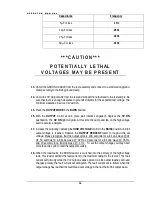
Capacitance
Frequency
5
µ
F or less
.1 Hz
10
µ
F or less
.05Hz
25
µ
F or less
.02Hz
50
µ
F or less
.01Hz
* * * C A U T I O N * * *
P O T E N T I A L LY L E T H A L
V O LTA G E S M AY B E P R E S E N T
13.
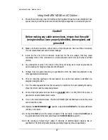
Uncoil the GROUND CABLE from the reel assembly and connect to a solid station ground.
Clamp securely to the trolley ground clamp.
14.
Uncoil the HV Output cable from the reel and connect the output lead to the test sample. Be
sure that there is enough clearance to grounded objects for the expected test voltage. The
minimum clearance in air is 10 kV ac/inch.
15.
Place the OUTPUT MODE in the BURN position
16.
With the OUTPUT control at zero (zero start interlock engaged), depress the HV ON
pushbutton. The HV ON light will glow. At this time the pump and fan on the high voltage
section will also energize.
17.
Increase the output by operating the HIGH VOLTAGE control to the RAISE position until full
output voltage is reached. Observe the OUTPUT PERCENT meter to rough in the set
voltage. Please recognize that the output cycle is: 100 seconds for a full sine wave @.01
Hz, 50 seconds fro a full sine wave @ .02 Hz, 20 seconds for a full sine wave @ .05 Hz,
and 10 seconds for a full sine wave @ .1 Hz. . To set the output voltage you may need
more than one cycle to read the output accurately.
18.
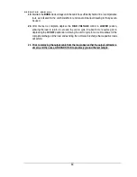
When the load faults, the BURN reactor is switched into the primary of the high voltage
tank. This reactor will limit the fault current to the maximum rating for the test set. The fault
current will flow only while the VLF output is above ground. As the output reaches zero and
changes polarity, the fault current will extinguish. The fault current will re-initiate when the
output voltage has reached the fault break-over voltage in the next half of the output wave.


