O P E R A T O R M A N U A L
15
7.
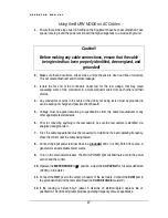
First, the cable capacitance must be measured to determine the best operating frequency.
Place the control near the cable being tested.
8.
Connect the input power terminal block to a grounded 230 v (+/-10%), 50/60 Hz source. A
generator is an acceptable power source.
9.
Turn on the main circuit breaker. The MAIN POWER light will illuminate at both the power
section and the control.
10.
Operate the METER MODE to
µ
F position. Adjust the CAP ZERO for full scale deflection
(ZERO) on the meter.
11.
Connect the HOT post to the center conductor of the test cable. Connect the COM post to
the grounded shield of the test cable. Read the CAPACITANCE scale(x10).
12.
If the reading is below 6.0
µ
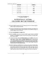
F (about 6 divisions on x10 multiplier) depress the x1
pushbutton. Then following table provides operating frequency versus capacitance.
Capacitance
Frequency
5
µ
F or less
.1 Hz
10
µ
F or less
.05Hz
25
µ
F or less
.02Hz
50
µ
F or less
.01Hz
13.
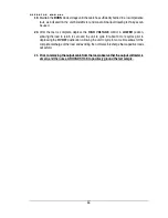
An oscilloscope (optional) can be connected to the SCOPE OUTPUT on the control for
wave shape monitoring. The oscilloscope should be properly grounded and the input should
be set to 1 volt/ division, the time base should be 5 seconds/division and the trigger should
be set to roll display to view the wave shape. An oscilloscope with signal memory display is
best used for this application. A BNC to BNC shielded jumper should be used for
connection between the SCOPE OUTPUT and the oscilloscope. A digital meter can be
used to monitor this connector. The voltage feedback calibration for this connector is 1 volt
for 10 kV of output.
* * * C A U T I O N * * *
P O T E N T I A L LY L E T H A L
V O LTA G E S M AY B E P R E S E N T


