background image

Description 

LS-R-4.8 

14 


1.8  Function parameters 
1.8.1  Measuring Range 

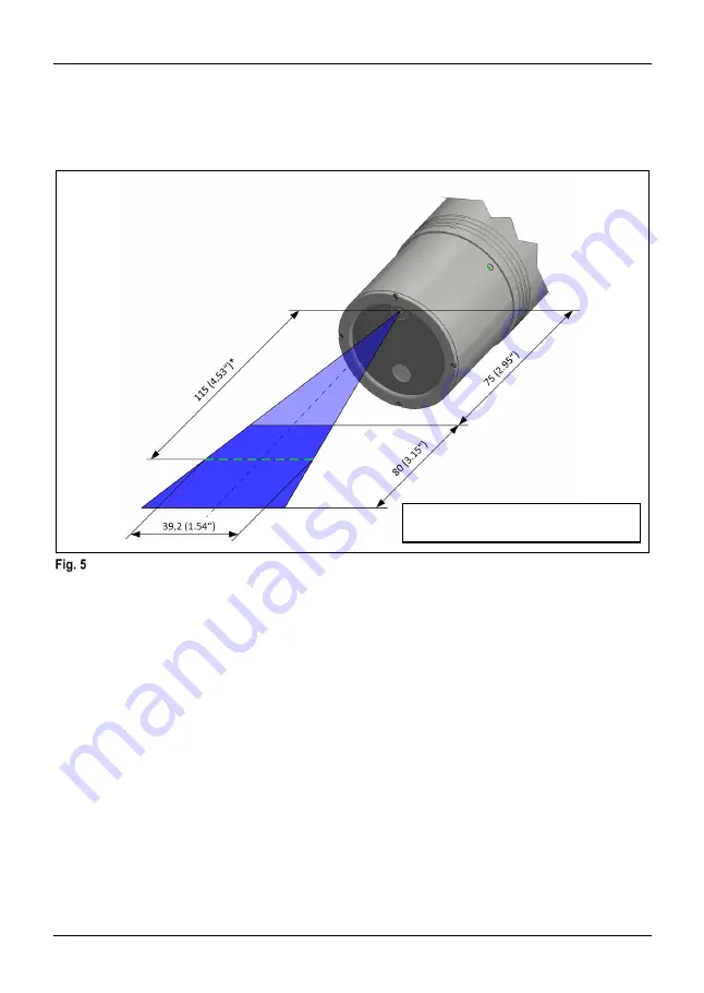
The following illustration shows the recommended average working distance and the permissible working range 

between the minimum and maximum possible working distance: 


Measuring Range 

* Distance is measured from outer housing 

  edge to average working distance. 

Summary of Contents for LS-R-4.8

Page 1: ......

Page 2: ...LANGUAGE DESCRIPTION PAGE DE BETRIEBSANLEITUNG 3 Manual Version V01 00 REV01 00 Release Date 2021 03 19...

Page 3: ...9 Transmission and Reception Area 16 1 10 Delivery Contents Accessories and Spares 17 1 10 1 Delivery Contents 17 1 10 2 Accessories General 17 1 10 3 Shanks 17 1 10 4 Spares 18 2 Operation 19 2 1 To...

Page 4: ...of Contents LS R 4 8 4 2 6 2 Error during operation 30 2 7 Maintenance and Cleaning 31 2 7 1 Cleaning the optical windows of the laser scanner 31 2 7 2 Cleaning the calibration sphere 32 2 7 3 Inspect...

Page 5: ...that if not observed could lead to property damage malfunctions INFORMATION INFORMATION indicates important information or helpful advices for the work with the described device 1 1 2 Safety Instruct...

Page 6: ...e at high speed can damage the laser scanner Make sure that the laser scanner is only used with no spindle rotation speed NOTICE Risk of damage to the equipment When the battery compartment is open th...

Page 7: ...These operating instructions are valid for the hardware available at the date of creation of these operating instructions The manufacturer reserves the right to make technical modifications 1 2 Purpo...

Page 8: ...comply with FCC and IC RF Exposure requirements the device must be installed and operated such that a minimum separation distance of 20 cm is maintained between the device and all persons during norm...

Page 9: ...LS R 4 8 Description 9 1 4 System Components System Components Laser scanner LS R 4 8 Radio wave receiver RC R 100 R RC R 100 R PT...

Page 10: ...ce 61 maximum working distance Zoom mode 2 Frame rate 80 Hz Raw points per line m 421 Raw point spacing m 65 minimum working distance 93 average working distance 122 maximum working distance Zoom mode...

Page 11: ...otal length L of the laser scanner system can be found in the accessories catalogue The total length L is the sum of the laser scanner length and the dimension X Battery compartment Customer specified...

Page 12: ...Description LS R 4 8 12 1 7 Markings Markings 2 3 4 5 6 7 1...

Page 13: ...sion window refer to chapter 2 4 1 3 Approval numbers for national and European radio approvals and conformity labels 4 Registered applicant for radio licenses 5 Compliance information for FDA Laser R...

Page 14: ...g Range The following illustration shows the recommended average working distance and the permissible working range between the minimum and maximum possible working distance Measuring Range Distance i...

Page 15: ...If the acquisition of measuring data is difficult when scanning dark shiny or transparent surfaces the gain factor should be set to one of the settings 4 or 5 However this setting and the resulting h...

Page 16: ...ated in the transmission area of the other device The range for a secure signal transmission is up to 15 m Transmission and reception area emission reception behaviour of antenna 0 1 0 100 of the maxi...

Page 17: ...ox consisting of 4x batteries type IMR26650 6401 4x cleaning cloths 4297 1x battery charger 6402 1x programming clip 6409 1x IR RAW stick 6259 1x Cylindrical pin 1 5x16 6412 1x USB 2 0 Extension 1 8 m...

Page 18: ...Description LS R 4 8 18 1 10 4 Spares Order Number Description Illustration 0506 Clamping screw...

Page 19: ...harger with quick charge 3 0 H00028517 2 2 Consumables for maintenance In addition to the supplied tools measuring and test equipment the following auxiliary equipment and consumables can be used for...

Page 20: ...ng screws from the shank 1 2 Remove shank 2 Mounting the shank 2 1 Slide the shank onto the laser scanner 2 2 Insert the clamping screws and tighten to the torque specified in Fig 7 3 Calibrate the la...

Page 21: ...polarity when inserting a new battery because the device will not work with wrong polarity The correct polarity is shown on the battery compartment by the corresponding symbols 2 Take the used battery...

Page 22: ...amming clip 2 Connect the USB port of the IR stick to the PC using the associated USB cable 3 Start the pairing program Pairing software 4 In the SET Configuration area enter the pairing information a...

Page 23: ...r manual INFORMATION After successful pairing the WLAN connection is set up to transfer the scan data This process is automatic and requires no further action by the user 10 After successful pairing d...

Page 24: ...spection Report delivered with the Scanner For reference the subsequent table shows sample data of the difference in accuracy between the actual used time and the stabilized accuracy at an environment...

Page 25: ...ad to the recording of incorrect measuring data Do not point the sensor directly at light sources during operation Dim or shade the direct light source if the sensor needs to be aligned directly with...

Page 26: ...MATION For the exact measuring of edges and special characteristics the sensor must be aligned across the areas to be measured If the sensor is aligned parallel to such workpiece geometries there is a...

Page 27: ...to avoid interruptions to the beam path as far as possible Interrupting the beam reflection 2 4 4 Direct reflections INFORMATION Depending on the profile and surface condition of the workpiece to be m...

Page 28: ...le and surface condition of the workpiece to be measured especially in the case of shiny or convex surfaces secondary reflections can occur This may mean that the measuring results are falsified To av...

Page 29: ...the LEDs Fig 16 and their meaning LEDs permanently blue approx 5 s Laser scanner starts after inserting batteries LEDs blinking green Laser scanner is transmitting signals LEDs blinking green red LOW...

Page 30: ...optical windows see chapter 2 7 1 The sensitivity has decreased or the recommended gain factor settings see chapter 1 8 2 do not allow the laser scanner to record measuring data Finger prints or dirt...

Page 31: ...hands or contaminate it otherwise Remove contamination from the optical windows before measuring Do not use aggressive cleaning agents as they may damage the optical windows 1 Wipe the optical windows...

Page 32: ...libration sphere when cleaning The calibration sphere may be damaged if it comes into contact with other objects e g when placed on a table Vigorous rubbing when cleaning may damage the surface which...

Page 33: ...h cleaning is performed entirely at own risk 1 Moisten a micro fibre cloth with isopropyl alcohol 2 Hold the calibration sphere by the shaft with one hand 3 Wipe the calibration sphere extremely caref...

Page 34: ......

Reviews: