background image

9

S

PECIFICATIONS

The specifications apply to all configurations using 
the RX 14-HL baseboard unless otherwise noted. 

Weight and output specifications vary per standard 
configuration.

Table 1: Technical Specifications for All RX 14-HL Baseboard Configurations

Housing Material

PA + 30% Glass Fill

Environmental 
Protection

IP 65 (Exceeds Nema 12/13)

Dimensions

Length:

9.7 in., 246 mm

Height:

11.7 in., 298 mm

Depth:

4.5 in., 115 mm

Note: These dimensions include the vibration mounts, antenna and sure seal 
connector.

Antenna

External

LED Diagnostics

Power/operation, TX signal reception, E-stop error, TX signal type

Inputs

4 On/Off isolated inputs at 12-24 Vdc. Inputs are fully programmable.

Frequency Range

419 MHz, 429 MHz, 434 MHz, 447 MHz, 458 MHz, 480 MHz, 868 MHz

RF Unit

Type CS synthesized with multiple frequencies

Typical Operating 
Range

Up to 300 ft., (100 m)

Safety Address

20-bit (over 999,999 individual possibilities)

Address Module (ADMO)

Safety

Active and passive Stop function

Parity & Checksum

Temperature 
Range

-11 to +158 degrees F (-25 to +70 degrees C)

Humidity Range

0 - 97% maximum non-condensing

Response Time

Less than 100 msec.

Baud Rate

Up to 9600 baud (selectable via H-Link)

Standard Features

Fully programmable via Pocket PC with H-Link modem

Built-in quick disconnect connector

Vibration mounts

Standard Options

MFSHL-232 serial link for H-Link programming

Summary of Contents for RX 14-HL

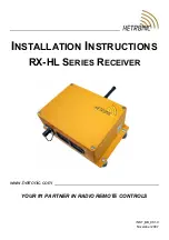
Page 1: ...www hetronic com YOUR 1 PARTNER IN RADIO REMOTE CONTROLS INSTALLATION INSTRUCTIONS RX HL SERIES RECEIVER INST_BB_001 0 November 2007...

Page 2: ...ing Your System 2 About Your Receiver 3 Description and Features 3 General Description 3 RX 14 HL Features 4 Mounting Your Receiver 5 Installing Your Output Wiring 6 Connecting Your Electrical Wiring...

Page 3: ...the following precautions to prevent accidental start up and possible injury or damage 1 Switch OFF the transmitter when it is not in use If equipped remove the key if the unit is placed any distance...

Page 4: ...YS confirm that the machine and radio remote control Stop functions work properly Understand all Safety Precautions provided in the manuals and review control functions and operation of the machine an...

Page 5: ...mitters See your transmitter documentation for detailed transmitter information Optional expansion boards may be installed within the receiver housing For more information regarding expansion boards c...

Page 6: ...PDT power relays and 1 Serial Peripheral Interface SPI to connect various expansion boards RX 14 HL FEATURES 1 E Stop output 4 optically isolated signal inputs 8 30Vdc or 48 240Vac 14 hardwired digita...

Page 7: ...lling Your External Antenna Optional on page 7 2 Drill 4 mounting holes See Drill Pattern and Hardware for illustration 3 Attach the receiver housing to the desired mounting surface Figure 1 Receiver...

Page 8: ...wires according to the wiring diagram of the machine and the radio remote control ATTACHING YOUR WIRING HARNESS Plug your wiring harness into the receiver and into the corresponding machine controls C...

Page 9: ...ort SPI 14 External Radio Frequency Module Port X5 6 RS232 Port 15 Status Lights LEDs Diagnostic 7 Voltage Supply Port 16 Mounting Screw Recesses Threaded 8 Address Module 2 17 Output Relays K1 14 wit...

Page 10: ...iver connection 5 to the antenna base 6 Do not overtighten Figure 2 Antenna Extension Diagram 4 Insert the mounting screws through the mounting screw holes 3 5 Secure the Antenna Wall Mount Holder 2 t...

Page 11: ...top error TX signal type Inputs 4 On Off isolated inputs at 12 24 Vdc Inputs are fully programmable Frequency Range 419 MHz 429 MHz 434 MHz 447 MHz 458 MHz 480 MHz 868 MHz RF Unit Type CS synthesized...

Page 12: ...on RX 14 HL Baseboard 1 7 kg 3 8 lbs 4 Digital 14 Digital RX 14 PT HL 1 8 kg 4 0 lbs 4 Digital 20 Digital 1 Prop X RX 14 PROP HL 1 8 kg 4 0 lbs 4 Digital 18 Digital 4 Prop X RX 22 HL 1 8 kg 4 0 lbs 4...

Page 13: ...afety devices and features are in place and operating correctly The operator is responsible for understanding and following all safety precautions in this and other applicable documentation MACHINE DA...

Page 14: ...signal On off control Latching control The function activates when the control is pushed and released The function stays on until the control is pushed and released again Mainline contactor The prima...

Page 15: ...apacitor type of surge suppressor EMC Electromagnetic Compatibility RF Radio Frequency EMI Electromagnetic Immunity RMS Root Mean Squared EEPROM Electrically Erasable Programmable Read Only Memory Rx...

Page 16: ...out the written permission of Hetronic Technical information subject to change without notice Hetronic reserves the right to discontinue make changes to and add improvements upon its products at any t...

Reviews: