


subwoofers have full, flat response and don’t need any corrections, that might cause
the amplifier saturation or distorsion.
•
The subwoofer connection phase determines acoustic results and needs to be
tested by being listened to. It might be necessary to invert it according to configuration,
main speakers and other electronic devices in the system. Make some listening tests
in both ways and choose the solution you prefer. See page Installation patterns -
Electric connection in phase and out of phase.
•
You can adjust bass also by changing the subwoofer position inside the trunk.
It is extremely difficult to know in advance the results you will get in your car
compartment and you’d better make some tests by moving the subwoofer box
and the port and speaker emitting direction. See page Installation patterns -
Placement.
Warning
•
In order to avoid possible damages, keep all components in their package until
you install them.
•
Always wear protective eyewear when using tools that may generate splinters.
•
Before you start your installation, turn off the head unit, the amplifier if you have
one, and all electrical devices in your audio system, in order to prevent any damages.
•
Make sure the location you chose for your speakers doesn’t hinder the correct
functioning of all mechanical or electric devices in your car.
•
Don’t put cables close to electronic gearcases.
•
Use extreme caution when cutting or drilling the car plate, verifying there are no
electrical wiring or structural elements underneath.
•
Protect conductor with a rubber ring if wires pass through a hole in the plate or
with proper materials if they pass close to heat-generating parts.
•
Firmly fix your subwoofer box to the vehicle chassis through brackets, screws,
nuts and bolts, to guarantee stability and safety while driving.
Warranty restrictions
Please carefully read warranty terms and keep both the manual and the original box.
HERTZ
has restricted warranty, according to the terms written below:
Warranty duration: 2 years.
This warranty is valid only for
HERTZ
products sold by
HERTZ
authorised dealers.
Products found to be defective during the warranty period will be repaired
or replaced with an equivalent product at
HERTZ
’s discretion.
Warranty is void:
1. For damages caused by accidents, abuse, improper operation, water, theft.
2. If after sale service is performed by anyone other than
HERTZ
authorised service
centers.
3. If serial number has been spoiled, altered or removed from the product.
4. For damages caused by overdriving or excessive distorsion due to non-linear
functioning of power supply.
HERTZ
accepts no liabilities for possible damages that result from disregarding
what is written in this manual.
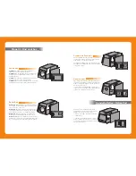
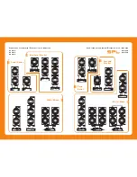
I disegni dei box riportati nel manuale sono semplicemente indicativi.
E' possibile progettare i box utilizzando soluzioni o geometrie differenti.
In ogni caso in fase di progettazione ricordate di:
• Utilizzare almeno una parete inclinata, per adattare il box al posizionamento in abitacolo,
per risolvere problemi di ingombro e per diminuire le risonanze interne al box.
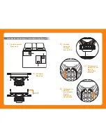
• Calcolare nel computo dei volumi l'ingombro dell'altoparlante che non è compreso nei
volumi indicati; se posizionerete l'altoparlante con il magnete dentro la cassa aggiungete
il Total driver displacement al volume della cassa stessa.
• Nel caso dei progetti in Reflex, Asymmetric Bandpass e Doppio Reflex, non aggiungere al
computo del volume totale l’ingombro dei tubi e dei condotti di accordo, ma solo il volume
del tipo di supporto utilizzato; es.: la tavola di legno nel caso del Condotto Reflex (Reflex Port).
• Evitare di posizionare la parete posteriore del box in prossimità del fondello dell’altoparlante.
Rispettate una distanza minima di 5 cm per non alterare il corretto funzionamento del foro
di ventilazione posteriore dell’altoparlante (vedi pagina Esempi di installazione - Distanza
dal fondo).
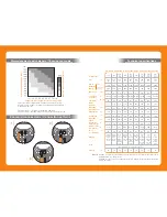
• Utilizzare del materiale fonoassorbente come il FONOFORM di AZ Audiocomp su tutte le
pareti interne di tutti i volumi.
• Nel caso si realizzi una cassa con accordo reflex tenete presente che la vicinanza del tubo
alle pareti interne produce un allungamento virtuale dello stesso, abbassando la frequenza
di accordo: se posizionate il condotto in prossimità di un angolo riducetene la lunghezza
di circa il 30%. Lo stesso prolungamento deve essere utilizzato per la realizzazione di
condotti laminari. Questo tipo di condotto può essere inoltre posizionato in ogni lato della
cassa, per risolvere eventuali esigenze di ingombro.
• La lunghezza dei condotti dichiarata nei vari progetti è comprensiva dell'allungamento
virtuale ed intesa per un montaggio ad angolo dei condotti circolari o per la realizzazione
di condotti laminari.
The boxes drawings you can find in this manual are only some suggestions.
You can design your own boxes by using different solutions or geometries.
When designing your box, however, please remember to:
• Use at least one slanted wall in order to make the enclosure fit the car compartment,
solve size problems and decrease the box internal resonances.
• Consider the speaker overall dimensions when calculating volumes since it is not included
in the indicated volumes; if you place the magnet speaker inside the box, add Total driver
displacement to the volume of the box itself.
• Not to add tubes and ports overall dimensions to total volume calculation in case of
Reflex, Asymmetric Bandpass and Double Reflex projects; you only have to add the
volume of the type of support you use (i.e. the wooden panel in case of Reflex Port).
• Avoid to put the box rear panel close to the speaker bottom plate. Place it at least 5 cm
far from it not to affect the correct functioning of the speaker rear vented hole (see page
Installation patterns – Distance from bottom).
• Employ some sound-proof material like AZ audiocomp FONOFORM to cover all the box
internal walls.
• Consider that when building a reflex box, the closer the port is to internal panels, the
longer it virtually seems, lowering frequency; thus, if you place the port next to a corner,
make it 30% shorter approximately. The same extention has to be used when building
rectangular ports. This type of port can be put in every corner of the box in order to solve
possible size problems.
• The ports and tubes length indicated in the projects includes this virtual extension and it
is recommended in order to mount reflex tubes in the corners or to build rectangular ports.
Avvertenze - Warning


