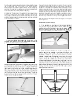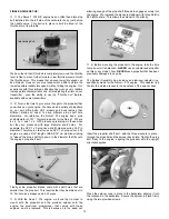
body and check to see if the bent end of the tubing is close to the
top of the tank. Pull the stopper out and adjust the tubing as
required. Keep checking the fit of the tubing inside the tank until it
is right. We always make it a habit to chamfer the bent end of the
overflow line to eliminate any blockage of air.
❑
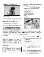
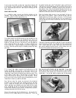
2) Use the shortest piece of aluminum tubing for the fuel
pick-up line. Insert the tubing through the rubber stopper. Fit the
smaller diameter rear metal clamping plate over the vent and fuel
pick-up tubes at the rear of the stopper. Adjust the two tubes as
needed to bring them close to the rear of this plate, leaving 3/16"
of tubing exposed for the fuel pick-up line.
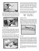
Slip the larger diameter front clamping plate over the two tube
ends at the front of the rubber stopper. Insert the clamping bolt
through the front clamping plate and through the rubber stopper
back to the rear clamping plate. With a screwdriver, thread the bolt
through the rear plate, bringing both plates in contact with the
stopper - do not tighten yet.
Insert the stopper assembly into the tank body. Adjust the stopper
to align the two tubes toward the top, in line with each other. Twist
the vent tube to align its inner bent end to the top center of the
tank body. This is the position that the tubes need to be in when
tightening the clamping bolt.
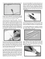
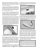
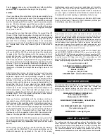
At the front of the stopper,
measure a point on both
aluminum tubes about
3/16" away from the front
face of the clamping plate.
Remove the stopper
assembly and cut the two
tubes at the marks just
made. Clean up their ends
with a sharp #11 blade and
sandpaper to remove any
burrs.
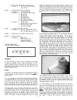
in position to the opposite side, against the elevators. As before,
apply 3 or 4 drops of thin CA glue to each exposed hinge edge.
Remove the tape and return the rudder to its neutral position.
Allow about 10 minutes for the glue to fully wick its way through
the surface of each hinge. Flex the rudder firmly in both directions
to free up its movement.
The bottom rudder hinge will likely interfere with the bottom
control horn hole – use a pointed object or small diameter drill bit
to clear out this hole to allow clearance for the rudder control horn
mounting "spikes".
❑
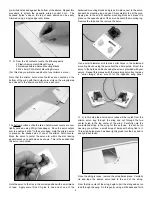
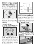
6) The tail wheel mounting plate is now secured to the bottom
rear of the fuselage with the two M2 x 6mm PWA screws included
with the tail wheel assembly. Slide the mounting bracket up to the
fuselage and hold it - centered in place - to the bottom of the
fuselage. Use a marking pen or pointed punch to mark the two
mounting-hole locations onto the fuselage. Drill two pilot holes at
the marks just made using a small drill bit. Attach the bracket to
the fuselage with the two PWA mounting screws.
FUEL TANK ASSEMBLY:
❑
1) The 2-ounce (60cc) fuel tank supplied with this kit is now
assembled. We suggest using a simple two-line system in this
airplane. One fuel line is connected to the "clunk" or fuel pick-up
line and the engine's carburetor. This line is also used to fill
the tank. The second line is the overflow or vent line and is
connected to the muffler pressure nipple, providing pressure to the
tank when the engine is running. This same line is also used
during fueling as the overflow line.
Note that the correct
orientation of the this tank, when installed in the fuselage, is the
"rounded" sides are the 'top' and "bottom" and the offset opening
at the front is toward the "top" of the tank body. The rubber
stopper for the tank has two holes all the way through it. Use
these two holes for the two aluminum tubes through the rubber
stopper.
Since the carburetor fuel nipple on the Norvel
™
.074 engine is
located on the right side of the engine, it is most convenient to
locate the fuel pick-up line on the right side of the fuel tank
stopper and the vent line on the left side of the stopper. NOTE:
The small diameter silicon fuel tubing pick-up line is inside the
tank body and should be removed now.
Inside the tank body, the vent line must reach up to - but not touch
- the top of the tank. To do this, the aluminum vent line is now
bent. Use the longest piece of aluminum tubing for the vent line.
Gently bend one end of the tubing up to about an 80
O
to 90
O
angle
- a Harry Higley Tubing Bender is perfect for this task. Insert the
unbent end of the tubing through the back of the rubber stopper
up to the bend just made. Insert the rubber stopper into the tank
8


