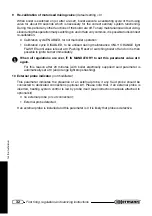
17
for the technician
Installation instructions
A
B
P
O
N C
M
F
E
D
I
H
L
G
t
u
p
n
i
t
a
e
h
r
i
e
h
t
n
o
g
n
i
d
n
e
p
e
d
,
s
r
e
l
i
o
b
t
h
g
u
a
r
d
d
e
c
r
o
f
r
o
f
s
l
a
n
i
m
r
e
t
e
u
l
f
f
o
g
n
i
n
o
i
t
i
s
o
P
g
n
i
n
o
i
t
i
s
o
p
l
a
n
i
m
r
e
T
s
e
c
n
a
t
s
i
D
s
e
c
n
a
i
l
p
p
A
*
W
k
4
m
o
r
f
W
k
7
o
t
m
m
.
n
i
m
W
k
7
m
o
r
f
W
k
6
1
o
t
m
m
.
n
i
m
W
k
6
1
m
o
r
f
W
k
5
3
o
t
m
m
.
n
i
m
w
o
d
n
i
w
a
r
e
d
n
U
A
0
0
3
0
0
5
0
0
6
t
n
e
v
r
i
a
n
a
r
e
d
n
U
B
0
0
3
0
0
5
0
0
6
r
e
t
t
u
g
a
r
e
d
n
U
C
0
0
3
0
0
3
0
0
3
*
*
y
n
o
c
l
a
b
a
r
e
d
n
U
D
0
0
3
0
0
3
0
0
3
w
o
d
n
i
w
t
n
e
c
a
j
d
a
n
a
m
o
r
F
E
0
0
4
0
0
4
0
0
4
t
n
e
v
r
i
a
t
n
e
c
a
j
d
a
n
a
m
o
r
F
F
0
0
6
0
0
6
0
0
6
*
*
*
s
e
p
i
p
n
o
i
t
a
u
c
a
v
e
l
a
t
n
o
z
i
r
o
h
r
o
l
a
c
i
t
r
e
v
m
o
r
F
G
0
0
3
0
0
3
0
0
3
g
n
i
d
l
i
u
b
e
h
t
f
o
r
e
n
r
o
c
a
m
o
r
F
H
0
0
3
0
0
3
0
0
3
g
n
i
d
l
i
u
b
e
h
t
f
o
s
s
e
c
e
r
a
m
o
r
F
I
0
0
3
0
0
3
0
0
3
r
o
o
l
f
r
e
h
t
o
n
a
m
o
r
f
r
o
d
n
u
o
r
g
e
h
t
m
o
r
F
L
0
0
4
0
0
5
1
0
0
5
2
y
l
l
a
c
i
t
r
e
v
s
l
a
n
i
m
r
e
t
o
w
t
n
e
e
w
t
e
B
M
0
0
5
0
0
0
1
0
0
5
1
y
l
l
a
t
n
o
z
i
r
o
h
s
l
a
n
i
m
r
e
t
o
w
t
n
e
e
w
t
e
B
N
0
0
5
0
0
8
0
0
0
1
o
n
g
n
i
v
a
h
,
e
c
a
f
r
u
s
r
e
h
t
o
n
a
g
n
i
c
a
f
e
c
a
f
r
u
s
a
m
o
r
F
.
s
t
m
3
f
o
e
c
n
a
t
s
i
d
a
n
i
h
t
i
w
s
l
a
n
i
m
r
e
t
r
o
s
g
n
i
n
e
p
o
e
l
o
h
n
o
i
t
a
u
c
a
v
e
e
h
t
m
o
r
f
O
0
0
5
1
0
0
8
1
0
0
0
2
n
i
h
t
i
w
s
l
a
n
i
m
r
e
t
r
o
s
g
n
i
n
e
p
o
h
t
i
w
t
u
b
,
e
v
o
b
a
s
A
e
l
o
h
n
o
i
t
a
u
c
a
v
e
e
h
t
m
o
r
f
.
s
t
m
3
f
o
e
c
n
a
t
s
i
d
a
P
0
0
5
2
0
0
8
2
0
0
0
3
*
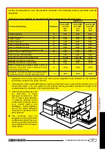
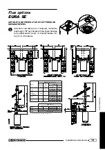
Appliances with an heat input lower than 4 Kw are not subjected to any limitation for the terminals
positioning, except for the points O and P.
**
The terminals under a practicable balcony must be positioned in such a way that the total flue run, from
the terminal outlet to its own outlet from the external balcony perimeter, included the height of the
eventual protection banisters, is no lower than 2000 mm.
*** In the terminal positioning, it will
be necessar y to keep
distances not inferior to 500
mm. in case of close proximity
to materials sensible to the
combustion products action
(e.g., plastic gutters and
downpipes, wood projections
and so on), unless adequate
measures of protection have
been adopted.
The terminals must be
designed in such a way that the
combustion products flow is as
much as possible ascensional
and protected from the tempe-
rature effects.
In case of evacuation to wall, the positions indicated in the following drawing and table must be
respected:


