background image

29

for the technician

First firing, regulation and servicing instructions

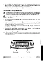
8. Repeat the following regulations: gas valve MAX-MIN pressure regulation, Slow Opening and

Max Heating Output, carefully following the instructions described in the previous pages.

9. Check that there are no gas leaks.

10. Apply the sticker indicating the type of gas (supplied with the kit) on the suitable area on “WARN-

ING” label inside the boiler.

Combustion check

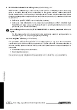
EURA has a special function for allowing flue checks. During this mode burner works at maximum
power regardless room thermostat and sanitary system.

— Prepare instrumentation for flue checking;

— while boiler is working (either in Winter or in Summer mode) keep knobs ‘Reset’ and 

pushed for 10 seconds. Boiler will ignite at maximum power and in the center of the display will
appear the code “07”. Heating will be flown to heating system;

— to stop burner press 

 ;

Note: Burner will automatically switch off when heating

system inlet temperature reaches 85°C. However,
after 15 min boiler will exit ‘programming mode’
and burner will stop.

Excluding automatic by-
pass

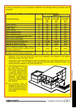
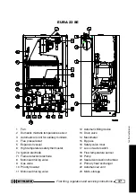
EURA are equipped with automatic by pass. In case
of complete opening, a flowrate sufficient for normal
boiler working is guaranteed. However, it is possible
to disconnect by pass, proceeding as follows:

1. Switch off boiler by pressing 

 .

2. Rotate screw located on to by pass (see 1 in the

attached picture) until it is in position “B”.

Normal by pass position is “A”.

VISTA DAL BASSO DELLA CALDAIA

1

Summary of Contents for EURA 23 E

Page 1: ...Quick guide Technical Data Installation adjusting and maintenance instructions User instructions GAS BOILERS EURA 23 E 28 E 23 SE 28 SE 32 SE ...

Page 2: ...by this symbol MUST be carefully respected so as to avoid any accident of mechanical e g wounds or contusions or general origin DANGER All warnings preceded by this symbol MUST be carefully respected so as to avoid any accident of ELECTRICAL origin fulguration DANGER All warnings preceded by this symbol MUST be carefully respected so as to avoid any accident of THERMIC origin scalds Attention All ...

Page 3: ...it must be connected to an heating system and or to a domestic hot water system in accordance with its features and power Packing items cartons nails plastic bags and so on must not be left within children easy reach as they are potentially dangerous Before any cleaning or servicing operation switch off the main electrical switch of the heating system and or any other suitable switch providing ele...

Page 4: ...ion and servicing instructions 21 Gaining access to manual regulation devices 21 Preliminary gas control 21 MAX MIN pressure adjustment on GAS valve 22 Regulation programming 23 Slow opening regulation 25 Max heating power regulation 25 Gas transformation 28 Combustion check 29 Excluding automatic by pass 29 Draining EURA boiler 30 Other boiler programme 31 Crypt Warnings for Technical experts 33 ...

Page 5: ...n o i t c e l e s e r u t a r e p m e T C 5 5 0 3 5 5 0 3 5 5 0 3 5 5 0 3 5 5 0 3 r e t a w t o h g n i t a e h y t i c a p a c k n a t i n i M l 9 0 2 3 9 0 2 3 9 0 2 3 9 0 2 3 9 0 2 3 A T A D L A C I R T C E L E y c n e u q e r f e g a t l o V z H V 0 5 0 3 2 0 5 0 3 2 0 5 0 3 2 0 5 0 3 2 0 5 0 3 2 n o i t p m u s n o c r e w o P n a f y t i c a p a c h g i h h t i w P A V W 0 0 1 0 3 1 P A V 0 ...

Page 6: ... 3 9 1 1 9 1 6 7 2 4 2 1 6 2 3 DIMENSIONS EURA 23 28 32 SE models only EURA AVAILABLE PUMP CAPACITY 1 EURA 28 available pump capacity closed By pass 2 EURA 28 available pump capacity automatic By pass 3 EURA 23 available pump capacity closed By pass 4 EURA 23 available pump capacity automatic By pass 5 EURA 32 available pump capacity closed By pass 6 EURA 32 available pump capacity automatic By pa...

Page 7: ...ature sensor 10 High temperature safety switch 11 Automatic air vent 12 Flue hood E and SE models 13 Flue thermostat E models Flue pressure switch SE models 14 Combustion chamber E models Fan SE models 15 Primary heat exchanger 16 Burner 17 Domestic minitank temperature sensor 18 Domestic minitank automatic air vent 19 Domestic heat exchanger 20 Gas valve 21 Motorised mixing valve 22 Priority flow...

Page 8: ...f 89 686 CEE 21 Dec 1989 Other Law number XXXX if any Other Law title and or brief description Directives Directive title and or brief description Always proceed with caution when handling the boiler and carrying out installation maintenance work as metal parts may cause injuries such as cuts and abrasions Wear gloves while doing the above mentioned operations Reference norms and laws for installa...

Page 9: ... INSTALLATION IN ROOMS WHERE TEMPERATURE CAN DROP DOWN TO 0 C When the installation place does not guarantee an adequate repair against atmospheric agents the gas boiler must be completely protected through an adequate coverage as a safety measure against the above agents In case of boiler installation in rooms where temperature can drop down to 0 it is advisable to protect the heating circuit wit...

Page 10: ...e template and hang boiler Remark The template is only used as a guide to align the pipework remove plastic caps and their relevant gaskets from boiler connections Remove bottom plastic supports by unscrewing their relevant screws Keep these screws since you will need them to install bottom grid Remark We suggest not to fix grid until the boiler is definitively commissioned Connect boiler to the p...

Page 11: ... is higher a PRESSURE REDUCER must be fitted upstream the boiler The cleaning frequency of the coil exchanger depends on the water supply hardness Besides the presence of solid residuals or impurities in the water for example in case of new systems could compromise the correct functioning of the boiler So may be necessary to install suitable water treatment device depending on the water features H...

Page 12: ... open filling tap slowly unscrew screw 2 located in water filling electro valve from position C to position A see picture taking care of all air vent installed in the system as soon as water flows out of air vent radiators close air vents check on the manometer 1 that pressure reaches the optimal value of 1 1 5 bar minimum 0 5 bar then reset screw 2 in position C closed repeat previous operations ...

Page 13: ...gas conversion f an interception valve must be installed upstream the appliance Open the meter valve and purge the air that is inside the system pipes including all the appliances While connecting gas inlet pipe of the boiler to the pipe coming from gas network it is MANDATORY to insert a TIGHT GASKET whose dimensions and material must be adequate Connection is NOT suitable for hemp teflon strip o...

Page 14: ...r Outdoor Temperatu re Probe SE are foreseen unplug GREEN connector from PCB and make connections as shown in the picture If TA is installed disconnect jumper X TA and SE terminals on green connector work at low voltage only connect NON POWERED wires coming from simple contact of Room Thermostat Chrono Thermostat and or Outdoor Temperature Probe DO NOT connect live wires for any reason Original He...

Page 15: ...ace here all necessary advices according to national rules about CHIMNEY CONNECTIONS of OPEN chamber boilers FLUE NO YES These diagrams are to explain the most important ITALIAN laws concerning chimney connections for EXAMPLE purpose only PRODUCTS TEST POINT 2500 mm MAX SLOPE min 3 2 x d min d ...

Page 16: ... is a slope of 2 5 downwards from the boiler to the out side see diagram This is essential to guaran tee correct boiler operation and reliability Air in let and flue outlet terminals should be protected by suitable approved flue accessories to avoid environmental elements penetration Place here all necessary advices according to national rules about CHIMNEY CONNECTIONS of SEALED chamber boilers 2 ...

Page 17: ... 0 5 0 0 8 0 0 0 1 o n g n i v a h e c a f r u s r e h t o n a g n i c a f e c a f r u s a m o r F s t m 3 f o e c n a t s i d a n i h t i w s l a n i m r e t r o s g n i n e p o e l o h n o i t a u c a v e e h t m o r f O 0 0 5 1 0 0 8 1 0 0 0 2 n i h t i w s l a n i m r e t r o s g n i n e p o h t i w t u b e v o b a s A e l o h n o i t a u c a v e e h t m o r f s t m 3 f o e c n a t s i d a P 0...

Page 18: ...to install the high capacity fan before flue kit avoiding any possible hindrance during assembling operations Provide electrical disconnection of the gas boiler and remove the sealed chamber closing 1 Take off screws A loosen screws B it is not necessary to take off screws B being the fan bracket provided with button holes and remove the standard fan disconnecting its cables for electrical supply ...

Page 19: ... Ø S C A C x a m n i m m S C x a m m m g a r h p a i D f o h t g n e L m S C A C r e t e m a i d m m E S 3 2 0 3 2 0 2 8 o t p u d 8 n a h t e r o m O N E S 3 2 h g i h h t i w n a f y t i c a p a c 0 6 1 3 0 4 O N E S 8 2 5 2 2 0 2 8 o t p u d 8 n a h t e r o m O N E S 2 3 0 2 2 2 1 6 o t p u d 6 n a h t e r o m O N s t c u d m m 0 8 Ø n o i t c e n n o c l a i x a o c n o r e t t i l p S s e p i...

Page 20: ...l 90 bend 1 linear meter 45 bend 0 5 meters D d use the diaphragm supplied with the boiler b available on request l e d o M m e t s y s l a i x a o c 0 0 1 0 6 Ø O L x a m n i m m V L x a m n i m m m g a r h p a i D V L r o O L m h t g n e l r e t e m a i d m m E S 4 2 4 5 0 5 1 1 o t p u b 4 4 2 o t 1 d 2 n a h t e r o m O N E S 8 2 3 5 0 4 1 1 o t p u d 1 n a h t e r o m O N E S 2 3 3 5 0 4 1 1 ...

Page 21: ...0 seconds before having the comple te control of the boiler Such delay can be temporary excluded through programming parameter n 9 see Regulation programming and it must be activated to guarantee perfect boiler working Gaining access to manual regulation devices 1 Unscrew screws located above boiler shift small blocking plate 1 remove front cover 2 lifting it up 2 To remove lower grid if any unscr...

Page 22: ... open more than one tap if needed wait for the stabilization of the pressure at least 20 seconds verify that pressure correspond to the MAX value indi cated in the table BURNER POWER PRESSURES see following pages unplug one of modulation coil supply connectors 4 and check that pressure correspond to the MIN value indicated in the table BURNER POWER PRES SURES then plug the connector back in if it ...

Page 23: ...default settings if not necessary GENERAL PROCEDURE With control panel in normal position open its cover and turn off boiler pushing knob green light flashes Keep both knobs Summer Winter and pushed for 5 seconds contemporary display shows service with a number on the left from here on called PARAMETER and another number on the right from here on called VALUE Select number of PARAMETER to be modif...

Page 24: ...er mode Normal 0 Always on 1 Always off 2 Default setting 0 See Other boiler programming for more info 6 Switching on delay after reaching set heating temperature from 0 to 7 minutes Default setting 3 See Other boiler programming for more info 7 Temperature difference between heating flow and domestic set from 10 to 20 C Default setting 15 C We advice to leave default setting unchanged 8 Minitank ...

Page 25: ... leakage Max heating power regulation Maximum heating power must be set according to actual heating system design Please find herewith table with power gas pressure values To regulate heating output proceed as follows Actual heating system power must be known according to plant design unscrew 2 3 rounds screw of gas valve pressure hole part 1 figure Gas valve and connect manometer while boiler is ...

Page 26: ...5 2 5 0 3 1 1 3 1 3 2 X A M 0 0 3 0 2 3 2 1 5 2 1 5 7 2 0 8 2 5 4 3 0 5 3 BURNER POWER PRESSURE TABLE EURA 28 E T U P T U O T A E H 0 2 G S A G L A R U T A N 0 3 G E N A H T U B 1 3 G E N A P O R P W k h l a c k r a b m H m m 2 O r a b m H m m 2 O r a b m H m m 2 O 0 1 1 N I M 0 3 6 9 5 2 5 2 5 1 5 6 1 6 2 1 0 2 3 0 1 0 3 0 3 2 7 2 7 9 8 1 9 3 1 0 8 1 1 1 6 3 7 3 7 8 9 8 0 1 2 0 1 4 1 0 4 0 2 1 2 ...

Page 27: ...8 0 1 2 0 1 4 1 0 4 0 2 1 2 4 3 4 8 9 0 0 1 8 2 1 0 3 1 5 1 0 0 9 2 1 5 1 5 1 1 2 1 1 5 4 1 8 4 1 6 1 0 6 7 3 1 6 5 7 5 8 1 1 0 2 1 6 1 3 6 1 7 1 0 2 6 4 1 2 6 3 6 3 1 2 3 1 8 7 1 1 8 1 8 1 0 8 4 5 1 7 1 7 9 4 1 2 5 1 0 2 4 0 2 9 1 0 4 3 6 1 6 7 7 7 6 1 3 6 1 5 2 2 9 2 2 0 2 0 0 2 7 1 3 8 4 8 8 7 1 1 8 1 4 2 4 4 2 1 2 0 6 0 8 1 9 2 9 5 9 1 8 9 1 5 6 2 0 7 2 2 2 0 2 9 8 1 5 9 7 9 7 0 2 1 1 2 8 2 5 ...

Page 28: ...over unscrew screws located above boiler shift small blocking plate 1 remove front cover 2 lifting it up On SE models open sealed combustion chamber 5 Disassemble pipe connecting Gas valve with burner 6 Remove ramp containing nozzles and substitute it with correct one using a 7mm spanner Reassemble ramp and pipe substituting gaskets On SE models close sealed combustion chamber L E D O M f o r e b ...

Page 29: ...oiler is working either in Winter or in Summer mode keep knobs Reset and pushed for 10 seconds Boiler will ignite at maximum power and in the center of the display will appear the code 07 Heating will be flown to heating system to stop burner press Note Burner will automatically switch off when heating system inlet temperature reaches 85 C However after 15 min boiler will exit programming mode and...

Page 30: ...pindle in position S If it is in position R open a domestic hot water tap to move it to S switch boiler off manually push spindle towards middle position where it can be blocked pushing towards inside position C Connect a rubber pipe to the draining tap 2 terminal put the other end of the pipe in a suitable drain or sink open draining tap anticlockwise when water pressure is COMPLETELY drained you...

Page 31: ...ops down and burner ignites again This parameter sets the minimum delay time between a switching off at set and the following re ignition We suggest the following criteria 0 Setting for fancoil system During heating boiler will ignite more frequently 1 7 Lower values are recommended for small plants and light radiators higher values for plants having big thermal inertia 7 Temperature difference be...

Page 32: ...Y ORANGE light FLASHES until value is reset at 0 Pushing Reset or switching boiler off and on it is then possible to ignite burner immediately When all regulations are over IT IS MANDATORY to set this parameter value at 0 again For this reason after 20 minutes with boiler electrically supplied said parameter is automatically set at 0 and orange light stops flashing 10 External probe indicator not ...

Page 33: ...be completed within 4 minutes Solution Before switching boiler off check water pressure on to the internal manometer in normal condition with cold water it should be 0 4 0 9 bar If problem is due to hydraulic system a lower pressure will be found Switch boiler off by pressing and disconnect electrical line Switch boiler on again and check water pressure on the internal manometer during filling If ...

Page 34: ...Modulation gas valve coil damaged short circuit Cause Control PCB has detected a short circuit in Gas modulation valve coil In this case coil is not fed and boiler works at minimum power Solution Unplug connectors from modulation gas valve coil and measure coil electric resistance 47 7 52 3 ohm at 20 C If it is found faulty replace it and regulate boiler otherwise check cables and electrical conne...

Page 35: ... inside the combustion chamber and replace them if necessary Check boiler ignition switching off and operation Check water and gas connections tightness Check gas consumption at the minimum and maximum output Verify that safety devices are correctly working Verify correct functioning of control and adjusting devices Verify periodically good working and efficiency of the combustion product evacuati...

Page 36: ...nsion vessel 6 High temperature safety thermostat 7a Ignition electrode 7r Flame detection electrode 8 Motorised mixing valve 9 Gas valve 10 Priority flowstat 11 Motorised mixing valve 12 Automatic filling device 13 Drain valve 14 Manometer 15 By pass 16 Safety valve 3 bar 17 Loss of water switch 18 Flow temperature sensor 19 Pump 20 Burner 21 Primary heat exchanger 22 Automatic air vent 23 Micro ...

Page 37: ...erature safety thermostat 7a Ignition electrode 7r Flame detection electrode 8 Motorised mixing valve 9 Gas valve 10 Priority flowstat 11 Motorised mixing valve 12 Automatic filling device 13 Drain valve 14 Manometer 15 By pass 16 Safety valve 3 bar 17 Loss of water switch 18 Flow temperature sensor 19 Pump 20 Sealed combustion chamber 21 Primary heat exchanger 22 Automatic air vent 23 Micro stora...

Page 38: ...ature safety thermostat 7a Ignition electrode 7r Flame detection electrode 8 Motorised mixing valve 9 Gas valve 10 Priority flowstat 11 Motorised mixing valve 12 Automatic filling device 13 Drain valve 14 Manometer 15 By pass 16 Safety valve 3 bar 17 Loss of water switch 18 Flow temperature sensor 19 Pump 20 Sealed combustion chamber 21 Primary heat exchanger 22 Automatic air vent 23 Micro storage...

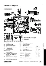
Page 39: ...e SR Flow temperature sensor TA Room thermostat TF Flue thermostat TS High temperature safety thermostat VD Three way valve VM Motorised mixing valve EVZ 1 2 3 Electro valve zone 1 2 3 AUX 1 2 3 Auxiliary for EVZ 1 2 3 TAZ 1 2 3 Room thermostat for zone 1 2 3 C Note if optional Remote Control is installed multizone heating wiring is different Refer to multizone heating diagram supplied with Remote...

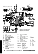
Page 40: ...ensor SE External temperature probe SR Flow temperature sensor TA Room thermostat TS High temperature safety thermostat VD Three way valve VM Motorised mixing valve EVZ 1 2 3 Electro valve zone 1 2 3 AUX 1 2 3 Auxiliary for EVZ 1 2 3 TAZ 1 2 3 Room thermostat for zone 1 2 3 C Note if optional Remote Control is installed multizone heating wiring is different Refer to multizone heating diagram suppl...

Page 41: ...on because a combustion products return can cause chronic or acute intoxications with danger of death If the thermostat must be replaced use the original spare part only In case of repeated interventions of the device check that the Flue Products Outlet System is efficient and made according to the laws in force see examples in Chimney connections WARNING for SE models The boiler is fitted with a ...

Page 42: ...ransfer the responsibility of the servicing and eventually of the operation to another person which must have the requirements indicated by the Law 46 90 Even if the user or the administrator decide to assume personally this responsibility ordinary servicing of the warm air heater and combustion checkings must be carried out by a qualified technician Warnings In case of gas smell a do not press el...

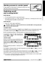
Page 43: ...er with set sanitary temperature in C Burner automatically switches on whenever there is a domestic hot water demand It is possible to change hot water temperature by pressing or new set temperature flashes for few seconds WINTER MODE Press knob to work boiler in WINTER mode WINTER mode is recognisable just looking on to display where both and symbols appear together with set sanitary and heating ...

Page 44: ...t changes Please always refer to instruction manual enclosed to room thermostat BOILER FILLING It is not necessary by end user to check water pressure inside boiler since EURA is provided with a special automatic filling device In case of anomaly a special alarm will be displayed Please refer to paragraph Boiler blocking and alarm codes ANTI FREEZING PROTECTION Eura is equipped with an Anti freezi...

Page 45: ...r 3 HEATING SYSTEMTEMPERATURE decrease knob 4 HEATING SYSTEMTEMPERATURE increase knob Pressing these knobs allows a decrease increase of 1 C in Heating flow water Such knobs work in winter mode only When you realize that room reaches too slowly desired temperature increase this setting If room temperature goes over desired temperature decrease this setting 5 DOMESTIC SYSTEMTEMPERATURE decrease kno...

Page 46: ...ESTIC SYSTEMTEMPERATURE displayed Set sanitary water temperature is shown It flashes for few seconds while changing tem perature by pressing or 12 Red light BOILER BLOCKED When red light is off boiler is normally working When red light is CONSTANTLY on a boiler failure which can be reset by end user happened and reset is displayed 18 and 20 in enclosed picture Please refer to Boiler blocking and a...

Page 47: ...20 RESET displayed Boiler is blocked Please refer to Boiler blocking and alarm codes to understand what happened restore boiler operation prevent future problems Boiler blocking and alarm codes In this section all alarm codes which can be displayed are described together with the relevant operations to be carried out by the USER to restore boiler operation If carrying out the described operations ...

Page 48: ...ti insects net which could have been dirtied by dust or by spider s webs Call a Qualified Technician when it is necessary place here references to national laws or rules about openings requirements if any If in the room where the boiler is installed there are fireplaces mantelpieces stoves coal stoves or similar fans for the Air Outlet such as wall fans aspiring cowls for cooking boards with outle...

Page 49: ...ic filling with water will dilute solution E19 Filling not completed within available time Red light flashing Alarm type service Solution call a Hermann Technical Centre qualified technician E21 Low water pressure in the primary heating system 3 automatic filling already executed Red light flashing Alarm type service Cause There is a water leakage inside your heating system Solution Switch boiler ...

Page 50: ...fter switching boiler on by pressing or after a reset it is necessary to wait 90 seconds During this period of time boiler does not work If a room thermostat is installed please check if it is regulated at a temperature higher then room temperature and that boiler is in Winter mode both symbols and must be displayed LOW DOMESTIC HOT WATER PRODUCTION Check if domestic hot water temperature is enoug...

Page 51: ...ly unused call a qualified technician to carry out all required operations checking in particular disconnection of gas water and electrical supplies On EURA E models only The installation of aspirators fireplaces or similar appliances in the boiler room and in adjacent rooms in case of indirect ventilation must be made in compliance with all specific safety rules and laws for example by augmenting...

Page 52: ...constantly improve its products Hermann Ltd has the right to change features and data written in the present manual at any time and without notice therefore this manual cannot be considered as a contract towards third parties HERMANN S r l Via Salvo d Acquisto 29010 Pontenure PIACENZA ITALY Tel 39 0523 510341 E MAIL export hermann it www hermann it GAS BOILERS ...

Reviews: