Part# 1002994-04
6/23/2010
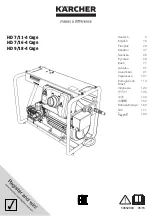
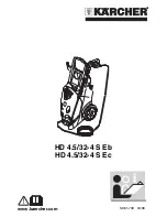
This manual contains important information concerning the
installation and operation of the gun washers listed above.
Read manual thoroughly and keep for future reference
INSTRUCTIONS
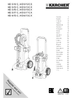
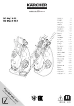
This manual contains important information concerning the
installation and operation of the gun washers listed above.
Read manual thoroughly and keep for future reference
INSTRUCTIONS
Herkules Equipment Corporation
2760 Ridgeway Court
Walled Lake, MI 48390-1662 USA
248-960-7100
800-444-4351
Fax 248 960-7109
Patents USA 7070167 4793369, 4960142, 5174317, 5193561, 5485860 Canada 1299468 & Patents Pending
website: www.herkules.us
Made in the USA
e-mail: [email protected]
Page 1 of 14