background image


15

13

12 11

10

9

8

7

6

5

4

3

2

1

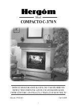
Hergóm


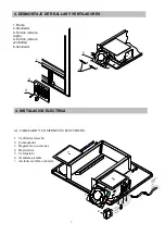
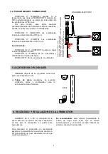
8- Chimney collar

securing screw

7- Collar and cover 

   Ø 125mm.

6- Hot air collar 

5- Hot air collar covers

4- Metal clamp

3- Flexible metal tube

2- Hot air grille

1- Chimney pipe

1

2

3

4
5

7
8

6


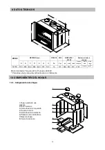
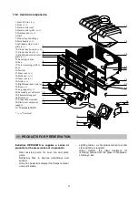
1. PRESENTATION


1.  Single body front 

2.  Hot air outlet grille  

3.  Deflector. 

4.  Inner rear of fireplace 

5.  Fireplace door handle  

6.  Inner sides of fireplace  

7. 

Air inlet grilles  

8. 

Cinder tray door handle  

9. 

Inside base of fireplace  

10. 

Cinder tray door  

11. 

Log support  

12. 

Fireplace door 

13. 

Outer duct 


2. INSTALLATION


The  form  of  installing  the  C.03-N  Compat 

Fireplace  will  decisively  influence  its  safety  and 
correct working order.


      It is very important for it to be well installed. 


      For  the  correct  installation  of  the  C.3.N  Compact 

fireplace and chimney, we recommend it be done by a 

professional. 


      The  C.3.N  Compact  fireplace  gives  its  heat  by 

radiation, heating walls, ceilings, etc. directly, although 

mainly  by  heating  the  air,  using  the  fans  it  has  fitted 

inside and  taking  the  heat  to  the  most  distant  parts  of 

the room.


2.1


HOT AIR OUTLET POSSIBILITIES. 

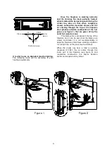
OUTLET THROUGH THE UPPER FRONT GRILLE (A)  

Loosen the screw located in the centre of the grille  

next  to  the  sliding  handle  indicated  with  the  mark  (C) 

and  slide  the  grille  sideways  to  close  and  open  the 

passage of hot air. 

OUTLET THROUGH THE HOOD (B) 

This option is not compatible with (A), and although the 

diagram  is  show  with  outlet  through  the  hood,  in  truth 

the collars located in the roof of the Compact fireplace 

are  designed  to  take  the  hot  air  to  adjoining  or  upper 

rooms. If you decide to use this installation, remove the 

covers  (5)  from  the  hot  air  collars  on  the  roof  of  the 

Compact Fireplace and cover up the upper grille on the 

front (A). The collars on the roof must be connected to 

the grilles with flexible metal tubes, preferibly heatproof. 

It  is  wise  for  holes  (normally  covered  by  grilles)  to  be 

placed in brickwork hoods  


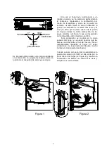
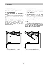
N.B.:

    When  installing  metal  tubes  for  smoke  evacuation, 

make  2  openings  in  the  lower  part  of  the  sides    of 
approximately  25x20  cm.  and  one  at  the  top  of  the  front  of 
approximately  50x20  cm.  to  favour,  through  natural 
convection,  the  outlet  of  hot  air  from  inside  the  cavity.  Thus, 
you will make the most of this heat and avoid possible cracks in 
the  hood.  These  holes  can  be  covered  with  decorative  grilles 
that  do  not  make  the  passage  of  air  excessively  difficult. 
INDUSTRIAS  HERGOM,  S.A.  has  this  type  of  grille 
available  and  can  supply  them  optionally  where 
required. 


Below  and  other  at  the  top to  prevent  hot  air  from 
concentrating, making natural circulation easier.


Summary of Contents for COMPACTO C-3/70 N

Page 1: ...g m Mod COMPACTO C 3 70 N INSTRUCCIONES PARA INSTALACION USO Y MANTENIMIENTO INSTRUCTIONS FOR INSTALLATION USE AND MAINTENANCE INSTRU ES PARA A INSTALA O UTILIZA O E MANUTEN O Edici n 29 04 2010 Cod C...

Page 2: ...ENVENIDOS a la familia HERGOM Agradecemos la distinci n que nos ha dispensado con la elecci n de nuestro Compacto C 3 N que representa en t cnica y estilo un importante avance sobre las cl sicas chime...

Page 3: ...lidad los collarines situados en el techo del Compacto est n dise ados para comunicar el aire caliente hacia estancias contiguas o superiores Si se decide por sta instalaci n quitar las tapas 5 de los...

Page 4: ...la chimenea etc pueden producir tiros inadecuados 2 2 2 Formaci n de creosota y su limpieza Cuando la madera se quema lentamente pueden producirse alquitranes y otros vapores org nicos en el conducto...

Page 5: ...ci n Acumulaci n de cenizas 45 d Evitar que el conducto desemboque en zona cercana a construcciones debiendo sobrepasar en altura a la cumbre m s pr xima si existe edificio colindante INCORRECTO CORRE...

Page 6: ...una vez al a o j La uni n de los tubos que forman la chimenea en el caso de los tubos met licos sencillos deben ser sellados con masilla refractaria La parte hembra de los tubos debe quedar siempre or...

Page 7: ...O Y COMPONETES ELECTRICOS 1 Ventilador derecho 2 Conmutador 3 Regleta de conexiones 4 Resistencia 5 Termostato 6 Arandela aislante 7 Aislante de fibra cer mica 2 3 1 4 5 1 Frente 2 Ventilador 3 Tornil...

Page 8: ...OS OPCIONALES HERG M dispone de los siguientes accesorios para este Compacto C 3 N a Tubos de acero recubiertos de esmalte vitrificado codos y sombreretes para la construcci n de la chimenea 6 ENCENDI...

Page 9: ...produce en la parte superior del hogar y se puede apreciar que las llamas son m s lentas y de color oscuro No es recomendable mantener el hogar en estas condiciones de funcionamiento durante mucho tie...

Page 10: ...adecuado acompa ado de las instrucciones de montaje y juntas 7 3 DE LA PLACA DEFLECTORA 1 Deslizar la placa deflector A hacia delante direcci n B hasta hacer coincidir los pivotes de sujeci n de los c...

Page 11: ...untas cristal tornillos etc e No debe situarlo cerca de paredes combustibles o que tengan alg n tipo de recubrimiento susceptible de deterioro o deformaci n por efecto de temperatura barnices pintura...

Page 12: ...cenicero 9 DATOS TECNICOS MEDIDAS mm POTENCIA PESO MEDIDAS DEL HOGAR Medidas m nima de la chimenea MODELO A B C D E G H Kw Kgs alto ancho fondo Tubo de chapa mm Tubo de obra Altura recom m C 3 70 N 70...

Page 13: ...ondo h f 23 Apoya troncos h f 24 Deflector aire secundario 25 Soporte de termostato 26 Resistencia 27 clema de conexiones 28 Soporte de componentes el ctricos 29 Termostato 50 C h f Hierro Fundido 11...

Page 14: ...ars WELCOME to the HERG M family We would like to thank you for the distinction you have made by choosing our C 3 N Compact fireplace which represents a great advance on classic wood burning chimneys...

Page 15: ...ing handle indicated with the mark C and slide the grille sideways to close and open the passage of hot air OUTLET THROUGH THE HOOD B This option is not compatible with A and although the diagram is s...

Page 16: ...aled or dirty door air inlets through the tube joints other appliance connected to the chimney etc may produce unsuitable draughts 2 2 2 Creosote formation and cleaning When wood is burned slowly tars...

Page 17: ...flat deviation Correct Accumulation of cinders 45 d Prevent the flue from ending in areas near to constructions and it must exceed the closest peak in height where there is an adjoining building INCO...

Page 18: ...ECT j Clean the chimney at least once a year j The joints of the tubes forming the chimney in the event of using simple metal tubes must be sealed using refractory filler The wider part of the tubos m...

Page 19: ...Fan right 2 Switch 3 Ceramic device 4 Resistance 5 Thermostat 6 Insulated washers 7 Insulated ceramic fiber 3 DISMANTLING GRILLES AND FANS 4 ELECTRICAL INSTALLATION 1 Front 2 Grille 3 Screw securing g...

Page 20: ...e a Steel tubes covered in vitrified enamel elbow joints and cowls for chimney construction 6 LIGHTING AND COMBUSTION ADJUSTMENT BY TURNING the cinder tray door handle from 0 to 90 more air is provide...

Page 21: ...in the top of the fireplace and it can be seen that the flames are slower and darker it is not recommendable to keep the fireplace under these working conditions for a long time as the glass may be s...

Page 22: ...propriate glass together with the fitting instructions and seals 7 3 THE DEFLECTOR PLATE 1 Slide the deflector plate A forwards direction B until the securing pivots on the sides coincide with the not...

Page 23: ...on near to combustible walls or those with a type of covering susceptible to damage or wear due to the temperature Varnishes paint etc Precaution must also be taken that the hot air grille is not plac...

Page 24: ...pipe mm Brickwork pipe Recomm height m C 3 70 N 700 550 635 455 460 315 145 10 107 368 534 370 150 170X170 5 6 Fan motor Voltage 220 v Power 2X13W For other heights consult your Distributor or the man...

Page 25: ...t side c i 2 Front c i 3 Hot air outlet seal 4 Hot air outlet grille c i 5 Fireplace door c i 6 Glass 7 Cinder tray door hinge 8 Door handle c i 9 Left hand cold air inlet grille c i 10 Cinder tray do...

Page 26: ...DOS fam lia HERG M Agradecemos a distin o que nos dispensou com a elei o do nosso Recuperador C 3 N que representa em t cnica e estilo um importante avan o sobre as cl ssicas chamin s de lenha O seu n...

Page 27: ...o dos colarins do tecto com as grelhas deve realizar se com tubo met lico flex vel preferivelmente calorifugado aconselh vel que nas chamin s de obra se pratiquem uns orificios normalmente cobertos p...

Page 28: ...cidade do vento Geralmente os ventos cont nuos fortes aumentam a tiragem mas os ventos tormentosos produzem diminui o da tiragem Temperatura exterior quanto mais frio no exterior melhor tiragem Press...

Page 29: ...e incombust veis N o montar tubos de fibrocimento b Escolher um tra ado o mais vertical poss vel N o ligar v rios aparelhos mesma chamin c Evitar que a conduta termine em zonas pr ximas a constru es...

Page 30: ...2 5 Montagem em chamin s existentes aconselh vel quando se aproveitam as chamin s existentes colocar um ou dois metros de tubo met lico pelo interior da mesma assegurando que a abertura que fica entre...

Page 31: ...s rio quando se utilize que esteja ligado rede el ctrica POSI O I CONFORTO Os ventiladores funcionam conjuntamente a 750 r p m POSI O II FORTE Os ventiladores funcionam conjuntamente a 1 500 r p m Rec...

Page 32: ...os gases quentes ver figura 1 que se desprendem do combust vel s lido madeira ou carv o Esta combust o produz se na parte superior do recuperador e pode se apreciar que as chamas s o mais lentas e de...

Page 33: ...ao nosso Distribuidor para que lhe forne a o vidro adequado 7 3 DA PLACA DEFLECTORA 1 Deslizar a placa deflectora A para a frente direc o B at fazer coincidir os pinos de fixa o dos laterais com as r...

Page 34: ...ntas vidro parafusos etc e N o instalar o recuperador pr ximo de paredes combust veis ou que tenham algum tipo de cobertura suscept vel de deteriora o ou deforma o pelo efeito da temperatura vernizes...

Page 35: ...zeiro 9 DADOS T CNICOS MEDIDAS mm POTENCIA PESO MEDIDAS INTERIORES Medidas m nimas da chamin MODELO A B C D E G H Kw Kgs Alt Larg Prof Tubo de chapa mm Tubo de obra mm Altura recom m C 3 70 N 700 550...

Page 36: ...undo f f 23 Apoia troncos f f 24 Deflector ar secund rio 25 Suporte de term stato 26 Resist ncia 27 R gua de liga es 28 Suporte de componentes el ctricos 29 Comutador 50 C f f Ferro Fundido 11 PRODUTO...

Page 37: ...ria Apartado de correos 208 de Santander 39080 SANTANDER Espa a Tel f 942 587000 Fax 942 587001 E mai hergom hergom com Rua da Arroteia 411 Apartado 1114 Le a do Balio 4446 957 S Mamede de Infesta Tel...

Reviews: