background image

Page 10

For technical questions, please call 1-888-866-5797.

Item 56844 


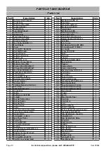
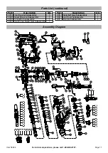
PARTS LIST AND DIAGRAM

Parts List

Part

Description

Qty

1

Hammer Rod Protector

1

2

Chuck Ring

1

3

Retaining Ring Ø26 

1

4

Support Washer

1

5

Rubber Ring

1

6

Lock Bead Sheath

1

7

Insert Block

2

8

Spring Rack

1

9

Flex Sheath Spring 

1

10

Retaining Ring Ø28

1

11

Direction Selector

1

12

Hex Socket Bolt M4

×

16

2

13

Front Shade

1

14

Cover

1

15

O Ring Ø13.94

×

Ø2.62

1

16

Dial Staff Sheath

1

17

Copper Sleeve

1

18

Mode Knob Spring

1

19

Mode Knob

1

20

Screw ST4.2

×

16 

13

20A Machine Screw M4

×

12 

1

21

Retaining Ring Ø42

1

22

Woolen Ring Ø30

×

Ø42

×

3

1

23

Oil Seal Ring Ø30xØ42x8

1

24

Hex Socket Bolt M6

×

25

4

25

Flat Washer Ø6

×

Ø10.5 

4

26

Front housing

1

27

O Ring Ø54.5

×

Ø2.2

1

28

Hammer Staff Sheath

1

30

Impact Hammer

1

31

Hammer Ring

1

32

Vibration Reducing Cushion

1

33

Limit Ring

1

34

Steel Ball SØ7.938 

8

35

Check Ring 

1

36

Spring

1

37

Ball Bearing 6907RS

1

38

Cylinder

1

39

Ratchet Spring Ring

1

40

Ratchet Spring

1

41

Ratchet Ring

1

42

Clutch Spring

1

43

Clutch

1

44

Steel Wire Block Ring Ø32

1

45

Large Cone-shaped Gear

1

46

Impact Piston

1

47

O Ring Ø21.1

×

Ø3.5

2

48

Gas Press Piston

1

49

Piston Pin 

1

50

O Ring Ø22

×

Ø2 

1

51

Connecting Rod Asm

.

1

51.1 Bushing

1

52

Oiliness Bearing Ø32

×

Ø37

×

12

1

53

Crank Housing

1

54

Machine Screw ST5.5

×

25

6

55

Oil Tank Cover

1

56

O Ring Ø25.12

×

Ø1.78 

1

57

Small Cone-shaped Gear

1

Part

Description

Qty

58

Ball Bearing 6904 VV

1

59

Final Gear

1

60

O Ring Ø5.5xØ1.05

1

61

Ball Bearing 608 RS

1

62

Crank Shaft

1

63

Ball Bearing 6004 

1

64

Retaining Ring Ø20

×

1

1

65

Crankshaft Gear

1

66

Crankshaft Gear Washer

1

67

Needle Bearing HK101410

1

68

Seal Ring

1

69

Inner Cover

1

70

Ball Bearing NSK 6201 DDU 

1

71

Oil Seal Ring Ø17

×

Ø32

×

7

1

72

Fan Guide

1

73

Screw ST4.8

×

58 

2

75

Stator

1

76

Armature

1

77

Inductor

1

78

Ball Bearing NMB 608D

1

79

Bearing Ring

1

80

Housing 

1

81

Carbon Brush 

2

82

Carbon Brush Wire

2

83

Machine Screw ST3.5

×

16

4

84

Coil Spring 

2

85

Fan Cover

1

86

Speed Control

1

87

Dual Indicator Lens

1

88

Flat Washer Ø5.5xØ14x1.6

2

89

Main Handle Seat

1

90

Shock Absorption Ferrule 

2

91

Shock Absorption Spring 

1

92

Shock Absorption Jacket

1

93

Main Handle

1

94

Trigger

1

95

Switch

1

96

Main Handle Cover

1

97

Cord Clip

1

98

Cord Armor

1

99

Cord

1

100 Split Pin Ø2

×

14

1

101 Shaft Pin Ø6

×

50

1

102 Bottom Shock Absorption Jacket

1

103 Hex Socket Bolt M6

×

20

2

104 Side Handle Asm. Steel Tie

1

106 T-Bolt M8

×

45

1

107 Side Handle Asm. Base 

1

108 Wing Bolt

1

109 Depth Gauge

1

110 Nut M6

1

111 Side Handle Cover

1

112 Side Handle

1

113 Electrical Field

1

114 Connector

2

115 Grease Tube

1

116 O Ring Ø16

×

3.3

2

117 Flat Washer Ø4

1

Summary of Contents for HE34

Page 1: ...21i WARNING To prevent serious injury User must read and understand Owner s Manual SAVE THIS MANUAL Bit not included When unpacking make sure that the product is intact and undamaged If any parts are...

Page 2: ...lert watch what you are doing and use common sense when operating a power tool Do not use a power tool while you are tired or under the influence of drugs alcohol or medication A moment of inattention...

Page 3: ...Tools for a replacement 10 Avoid unintentional starting Prepare to begin work before turning on the tool 11 Do not lay the tool down until it has come to a complete stop Moving parts can grab the surf...

Page 4: ...eases you must use a heavier gauge extension cord Using extension cords with inadequately sized wire causes a serious drop in voltage resulting in loss of power and possible tool damage See Table A 3...

Page 5: ...injury Symbology Double Insulated V Volts Alternating Current A Amperes n0 xxxx min No Load Revolutions per Minute RPM WARNING marking concerning Risk of Eye Injury Wear ANSI approved safety goggles w...

Page 6: ...t should not come out when pulled 6 To adjust the Front Handle twist it to loosen it rotate it as needed and retighten it securely Workpiece and Work Area Set Up 1 Designate a work area that is clean...

Page 7: ...ol in 5 Set the bit against the work area CAUTION Keep power cord away from moving machines 6 Place one hand on the Front Handle and the other hand around the Handle 7 Press the upper part of the Trig...

Page 8: ...LURE Do not use damaged equipment If abnormal noise or vibration occurs have the problem corrected before further use Cleaning Maintenance and Lubrication 1 BEFORE EACH USE inspect the general conditi...

Page 9: ...rd 1 Allow tool to work at its own rate 2 Keep cutting bits sharp Replace as needed 3 Wear ANSI approved safety goggles and NIOSH approved dust mask respirator while blowing dust out of motor using co...

Page 10: ...ushing 1 52 Oiliness Bearing 32 37 12 1 53 Crank Housing 1 54 Machine Screw ST5 5 25 6 55 Oil Tank Cover 1 56 O Ring 25 12 1 78 1 57 Small Cone shaped Gear 1 Part Description Qty 58 Ball Bearing 6904...

Page 11: ...assembly 1 Parts List continued 20A 807 76 77 78 61 67 69 70 71 806 62 63 64 65 805 28 21 22 23 26 57 58 801 804 59 60 802 51 51 1 803 31 32 33 34 38 35 36 37 116 30 1 2 14 3 4 6 7 8 9 10 11 59 58 64...

Page 12: ...arges prepaid Proof of purchase date and an explanation of the complaint must accompany the merchandise If our inspection verifies the defect we will either repair or replace the product at our electi...

Reviews: