


Chapter – VIII
A s s e m b l y o f T h e E l e c t r i c M o t o r
( Assembly Group 7 )
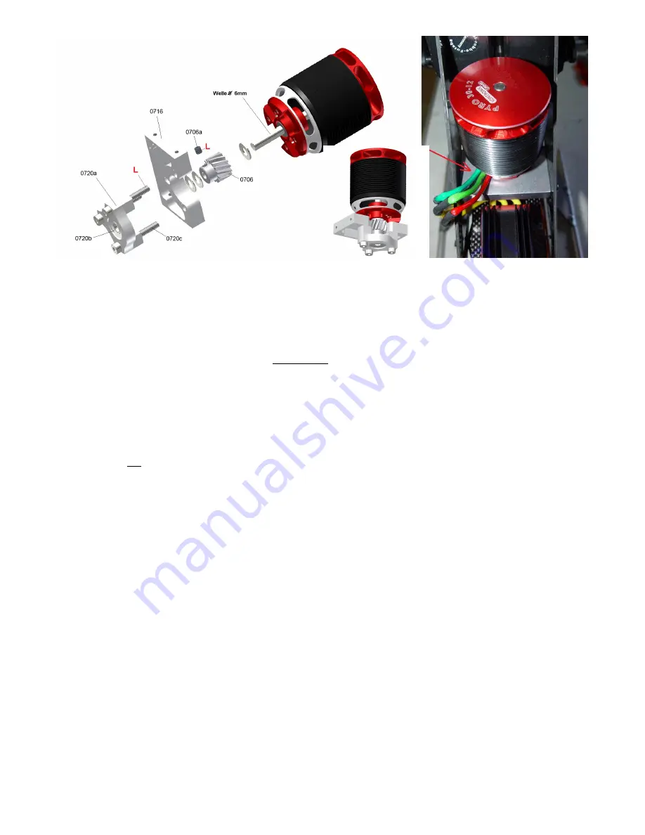
The picture above shows the assembly of the recommended Pyro 700-52 motor with standard shaft and M4 attachment holes
on a 30mm hole circle. The motor support plate can also be used for different motors with a 25mm hole circle with M3
screws.
For Scorpion motors the counter bearing is not needed and the motor can be attached directly to the plate 0716 using shorter
screws. Because of the higher temperature which is generated from Scorpions it is even better not to use the counter bearing
because it will generate unnecessary additional heat.
At first solder the 3.5mm or 4mm gold plug to the unshortened motor cables of the motor.
The pinion is manufactured with a countersink in such a way that it can be used for a continuous 6mm shaft (Pyro) and for
the Scorpion shaft 8mm to 6mm or 10mm to 6mm as well. Between the pinion and the motor bearing a 0.5mm thick washer
has to be used. Different types of 0.5mm thick washers 6mm, 8mm and 10mm are included in the bag (
Motor fastening
)
Attention!
On the Scorpion motor at first the c-clip of the shaft has to be removed. You will not need it anymore because the
pinon will keep the shaft in the right position later (look also at the detailed description on the next page).
At first the pinion 0706 has to be mounted provisionally on the shaft using a suitable spacer washer. Tighten the grub screw
loosely only (do not use Loctite yet).
The counter bearing support 0720a with the bearing 0720b is tightened through the motor fastening plate to the motor using
the three M4x30 screws 0720c (only for the Pyro).
Attention!
Make sure that there is no pressure applied to the motor shaft or the pinion when tightening the three attachment
screws. This causes tension to the bearings. So make sure that the screws are tightened step-by-step and alternately to
avoid tension to the motor shaft on the side (only tighten the screws provisionally without using Loctite).
Following the motor frame plate has to be pushed between the chassis frame plates and attached to the provided elongated
holes of the chassis frame plates using the M3x12 screws 0716a und the thick brass washers 0716b. Do not yet tighten the
screws, so that you can easily move the motor in the elongated holes. Press the plate with the motor vertically down, so that
the attachment screws rest on the lower edges of the elongated holes. Hereby the motor is positioned angularly to the
chassis. Push it against the gears of the indermediate shaft.
Attention!
Watch the gears from the side through the large cutout in the chassis and check if the motor pinion and first step
plastic gear are positioned at the same height. Additional washers have to be used between motor bearing and pinion if the
bottom side level of the steel pinion 0706 is more than 0.5mm higher then the bottom level of the gear 0506.
Disassemble the entire motor frame plate with the motor again and fill up the gap between the pinion and the counter bearing
with different of the enclosed 6mm washers.
Attention! It is very important that a little gap of 0.1 to 0.2mm is left between the counter bearing and the bottom of the pinion
so that tere is no axial pressure onto the counter bearing after tightening the three M4 screws.
Finally tighten the three motor mounting screws and the grub screw again (use some Loctite).
23


