


5
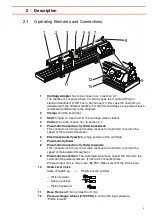
2 Description
2.1 Operating Elements and Connections
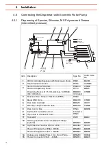
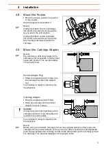
1
Cartridge Adapter
has to be chosen acc. to section 4.7.
The feedline is connected here. In certain cases the mounted fitting for
standard feedline OD 3/8" has to be changed. In this case the new fitting is
delivered with the different feedline. For Gel CA cartridges a supporting sleeve
is delivered additionally to the adapters.
2
Clamp
s hold the shell tight.
3
Shell
, hinged, to insert and fix the cartridge (when closed).
4
Pusher
has to be chosen acc. to section 4.7.
5
Pneumatic Connection: Cylinder backwards
.
This connector is a flow control valve (exhaust air restrictor) to control the
speed of the forward movement.
6
Electrical proximity switch
, empty position of the cartridge.
7
Pneumatic Cylinder
8
Pneumatic Connection: Cylinder forwards
.
This connector is a flow control valve (exhaust air restrictor) to control the
speed of the backward movement.
9
Pneumatic Connection
. The calibrated pneumatic hose OD 6 mm from the
controller (Regulated pressure:
I
) has to be connected here.
Pressure input limit is max. 4 bar (58 PSI). Make sure that the limit is kept.
10
Hand Lever Valve
State of Switching = Position of the cylinder
– Piston forward
– Keep in position
– Piston backward
11
Base Frame
with fixing holes Dia. 9 mm.
12
Pressure Gauge 0-6 bar (0-100 PSI)
to control the input pressure
“Piston forward”.
1
2
3
4
5 6 7
8
9
10
11
97631
12


