background image

DECALS


DECALS - TT - TUBE TABLE.DOC 


6. 

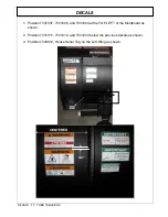
Position 7300047 Manual Canister on the Angle Brace, Left of Center, 
Outboard of Trip Device when possible.  


7. 

Position 7331009 Left of External Compression Trip on Moldboard when visible. If not 
visible, place on Moldboard forward of upper ECT knuckle. 


8. 

Position 7331009 On Enclosed Spring Trip Canisters when applicable. 
 

Centered 

1 3/4" 

7331009 Forward 

of Knuckle 

7331009 
Outboard 
of Knuckle 

Summary of Contents for 42RIS TT

Page 1: ...vy Duty Trucks PARTS BOOK AND INSTALLATION MANUAL SERIAL NUMBER ______________________ VERSION 3 2 NOVEMBER 2014 HENKE MANUFACTURING CORPORATION MANUFACTURERS OF SNOW REMOVAL EQUIPMENT FOR 95 YEARS 3070 WILSON AVE LEAVENWORTH KS 66048 PHONE 913 682 9000 FAX 913 682 0300 WEBSITE ADDRESS WWW HENKEMFG COM EMAIL PARTS HENKEMFG COM ...

Page 2: ...TUBE_TABLE_PLOW_EFF_NOV09_TO_PRES_8400030_032 DOCX Page 2 of 32 THIS PAGE IS INTENTIONALLY LEFT BLANK ...

Page 3: ...itride rods Steel Integral shield prevents snow from blowing over top of moldboard Water drainage ports in ribs to prevent water from pooling when plow is stored Cushion relief valve and hydraulic quick couplers standard Moldboards available in a variety of sizes with and without discharge ears mouse ears Multiple trip hitch and running gear options available Wide variety of cutting edges curb gua...

Page 4: ...mary 6 Setup and Operation 7 Maintenance 8 Section 2 Installation Diagrams Parts lists 10 Hydraulics Installation Instructions 12 Section 3 Running Gear 16 Section 4 Trip Devices 24 Section 5 Swivel Plates Plow Portion Hitches 26 Section 6 Cutting Edges Curb Guards Wear Guards 28 Section 7 Warranty Policy Procedure 31 ...

Page 5: ...ession Trip Assembly ECT 25 FIGURE 5 1 Universal Quick Hitch UQH 26 FIGURE 5 2 Swivel Plates Plow Hitches 27 List of Tables TABLE 2 1 Henke Tube Table Plow Parts List 11 TABLE 2 2 Hydraulic Components Not Shown in Figure 2 1 13 TABLE 2 3 Cable Level Lift Assembly 14 TABLE 3 1 Spring Loaded Running Gear Parts list 17 TABLE 3 2 Henke 8 Steel Wheel Assembly Parts List 18 TABLE 3 3 Mushroom Shoe Assem...

Page 6: ...TUBE_TABLE_PLOW_EFF_NOV09_TO_PRES_8400030_032 DOCX Page 6 of 32 THIS PAGE IS INTENTIONALLY BLANK ...

Page 7: ...Safety Section 1 1 2009 Alamo Group Inc SAFETY SECTION ...

Page 8: ...ECOME ALERT YOUR SAFETY IS INVOLVED The Symbol and Signal Word are intended to warn the owner operator of impending hazards and the degree of possible injury faced when operating this equipment Indicates an imminently hazardous situation that if not avoided WILL result in DEATH OR VERY SERIOUS INJURY Indicates an imminently hazardous situation that if not avoided COULD result in DE ATH OR SERIOUS ...

Page 9: ...de nly in an em ergency Never allow inexperienced or untrained personnel to operate the Truck or Power unit and Snow Plow witho ut supervision Make sure the operator has fully read and understood the manuals prior to operation SPNG 4 In addition to the design and configuration of this Snow Plow including Safety Signs and Safety Equipment hazard control and accident prevention are dependent upon th...

Page 10: ...alcohol immediately before or while driving or operating the Snow Plow Drugs and alcohol will affect an operator s alertness and coordination and therefore affect the operator s ability to operate the Equipment safely Before operating the Equipment an op erator on prescription or over the counter medication must consult a medical professional regarding any side ef fects of the medication that woul...

Page 11: ...nd Truck or Power unit It is recommended that the operator wear appropriate clothing take scheduled work breaks to help prevent these potentially impaired operating conditions If pos sible completely shut down the Equipment exit the cab and warm the body in a properly heated area Never operate the Equipment in a fa tigued or impaired mental state that effects the proper and safe Equipment operatio...

Page 12: ...ed debris and foreign objects If yo u are unable to see these types of items discontinue operation until visibility improves SNPO 8 When transporting the Snow Plow be tween locations follow all local traffic laws and regulations SNPO 10 Operate at a speed that allows you to safely operate and control the Truck and Snow Plow Safe plowing speed depends on street condition and the type and amount of ...

Page 13: ...aterial SNPO 25 Always wear required OSHA approved Personal Protective Equipment PPE when coming in contact with and removing potentially dangerous and hazardous material that ha s collected on the Snow Plow equipment or which is obstructing one or more components Pay close attention to dangerous and hazardous material including but not exclu sively limited to chemicals decaying carcasses and shar...

Page 14: ...animals are within 25 feet of the e quipment basket when dump ing contents from or clea ning the Snow Basket Bucket contents which may exceed several thousand pounds could fall and crush a bystander or an animal resulting in possible injury or death SNPO 34 Use extreme caution when operating the Equipment in traffic To alert motorist of the Equipment s presence use all equipped warning signals to ...

Page 15: ...nt is pr operly attached to the Power Unit and the r etaining pins securely lock the Implement into position Improper mounting of the Imp lement onto the Power Unit can result in the Implement falling causing serious injury SNPC 02 The operator of the equipment must be tr ained in the operation and safe use of this machine The operator must read and completely understand the operator s manuals of ...

Page 16: ...gs Make sure all pins are secure and safety pin equipped Make sure replacement parts are the correct size and properly installed Make sure all fluid levels are full and replenish as necessary Make sure fuel oil and coolant caps are replaced and tightened Check tire condition for tread wear and tire pressure at the rated PSI Make sure that all safety shields and guards are attached and in good cond...

Page 17: ...ible serious injury from broken blade being ejected from plow SNPM 10 Escaping pressurized hydraulic oil generated by hydr aulic pumps has the potential to inflict serious injury and possible death Never attempt to repair a pump or hose or tighten a connection while the system is pre ssurized Always shu t down the engine and relieve hydraulic oil pressure before performing any repairs to the hydra...

Page 18: ...cleansers and any other chemical agent SNPM 22 Battery posts terminals and related accessories contain lead and lead compounds chemicals known to the state of California to cause cancer and birth defects or other reproductive harm Wash Hands after handling SNPM 23 Avoid contact with hot surfaces on the bottom of the skid shoes or plow cutting edges Use gloves and eye protection when servicing hot ...

Page 19: ...ease the speed of the Truck the stopping distance increases Determine the maximum safe transport speed for you and the equipment When driving down a hill or on wet or icy roads the braking distance increases use extreme care and reduce your speed Do not operate the equipment with weak or faulty brakes Obey all traffic laws and regulations Never exceed the posted speed limit The Snow Plow has moved...

Page 20: ...nt with which the employee is or will be involved Employer Responsibilities To ensure employee safety during plow and truck or other power unit operation it is the employer s responsibility to 1 Train the employee in the proper and safe operation of the plow and truck or other power unit 2 Require that the employee read and fully understand the plow and truck or other power unit Operator s manual ...

Page 21: ...Version 1 0 12 15 09 DECALS TT Tube Table doc Kit Revision Notes TT TUBE TABLE PLOW ...

Page 22: ...7330012 1 Serial Number Tag 7330023 4 Serial Tag Tacks 7300047 1 Product Manual Canister 7300048 1 Plug for Product Manual Canister 7020391 3 Stud 1 4 20 x 5 8 Non Flange 7040002 3 Flat Washer 1 4 USS 7030044 3 Nylock Nut 1 4 20 Other Attachments and Decals Use the following decals from sheet 7332006 010 NOTE Some decals on sheet 7332006 010 are not needed on this product Discard decals not needed...

Page 23: ...31007 7331005 and 7331004 at the TOP LEFT of the Moldboard as shown 2 Position 7331011 7331012 and 7331003 below the previous decals as shown 3 Position 7330012 Henke Serial Tag on the Left Wing as shown 3 4 CENTERED Center 7330012 on bottom angle ...

Page 24: ...DECALS DECALS TT TUBE TABLE DOC 4 Position 7331010 Qty 2 AND 7331006 Qty 2 as shown 7331006 7331010 3 4 Minimum ...

Page 25: ...DECALS DECALS TT TUBE TABLE DOC 5 Position 7330014 Henke Logo in CENTERED 3 4 ...

Page 26: ... of Trip Device when possible 7 Position 7331009 Left of External Compression Trip on Moldboard when visible If not visible place on Moldboard forward of upper ECT knuckle 8 Position 7331009 On Enclosed Spring Trip Canisters when applicable Centered 1 3 4 7331009 Forward of Knuckle 7331009 Outboard of Knuckle ...

Page 27: ...g the 7 16 chain link in the top center slot of the arm end plate Raise plow and check for proper 10 ground clearance at the cutting edge Adjust chain if necessary to accomplish 10 clearance For Husting hitch designs no lift chain is used and ground clearance of 8 10 is acceptable Runner shoe adjustment if equipped Raise plow retract running gear Lower plow so the cutting edge is touching the grou...

Page 28: ...lts after the first 8 hours of use and to regularly check for loosened or missing fasteners Replace any damaged or missing fasteners immediately Because of the environment in which snow equipment is expected to operate hydraulic lines fasteners wearable or replaceable items and warning decals may become damaged by snow ice and road debris These items must be inspected daily and replaced if necessa...

Page 29: ...of oil or grease on exposed rod surfaces FRAME AND MOLDBOARD JOINTS Check pins bushings and pivot bolts for wear Make sure all keepers are in place Make sure shear bolts and pins are same as original equipment usually grade 2 Some drivers don t like replacing shear pins and will install grade 8 replacements to avoid replacing during a storm These items are designed to shear to protect the driver a...

Page 30: ...TUBE_TABLE_PLOW_EFF_NOV09_TO_PRES_8400030_032 DOCX Page 10 of 32 FIGURE 2 1 Tube Table Plow ...

Page 31: ...GR 5 22 3 7030099 Nylock Nut 1 1 4 7 23 1 7080594 Hydraulic Cylinder 4 x 12 x 2 w Yoke 24 1 Call Henke A Frame 25 1 7050043 Cotter Pin 3 16 x 2 5 26 1 Varies See Section 6 Swivel Plate Plow Hitch 27 2 7040014 Flat Washer 1 1 4 Hardened SAE 28 1 7030023 Slotted Nut 1 1 4 7 29 1 1300 0372 Swivel Bolt 30 1 7080593 Hydraulic Cylinder 4 x 12 x 2 w Ear 31 2 7030086 Nylock Nut 5 16 18 32 2 7040003 Flat W...

Page 32: ...t Adapter 8 JIC M x 8 ORB M 2 7090014 Straight Adapter 8 JIC M x 10 ORB M 2 7090235 Elbow 90 08 JIC M x 8 JIC F 2 7090507 Elbow 90 8 ORB Adj Male to 08 JIC Swivel Female 2 7090284 Elbow 45 08 JIC Male to 10 ORB Adj Male Qty Henke Part No Description 2 7090543 Quick Coupler Male 8ORB 2 7090544 Quick Coupler Female 8ORB 1 7090405 Dust Plug for 7090544 on Truck 1 7090406 Dust Cap for 7090543 on Truck...

Page 33: ...r Looking Right and Down from Left Side of Push Frame TRUCK TRUCK 2 7110601 38 Hose 2 7090284 Elbow 45 2 7090014 Straight 2 7090235 Elbow 90 2 7110661 60 Hose 2 7090290 Straight 2 7090378 Tee 2 7090507 Elbow 90 2 7090257 Elbow 90 2 7080424 Cushion 2 7020372 Bolt 2 7030086 Nut 2 7040003 Washer 2 PLCs 2 7020170 Rod End Bolt 2 7030099 Nylock Nut 2 7110748 19 Hose 2 7110748 2 7110601 2 7110661 1 70203...

Page 34: ... 4 1 7020082 Hex Capscrew 3 4 10 x 3 5 GR 8 5 2 7020051 Hex Capscrew 1 2 13 x 3 5 GR 5 6 2 7030101 Nylock Nut 1 2 13 7 1 7030030 Toplock Nut 3 4 10 GR C 8 6 7060012 Cable Clamp 1 2 9 2 7060001 Shackle 7 16 2 Ton 10 2 7060013 Cable Thimble 1 2 TABLE 2 3 Optional Cable Level Lift Assembly Parts List FIGURE 2 3 Optional Cable Level Lift Assembly NOTE Must use double acting lift cylinder on truck hitc...

Page 35: ...t arm reaches horizontal position Adjust chain lengths as necessary 6 Lift the plow off ground approximately 12 then with plow in air rotate plow side to side and verify that plow remains approximately level in all positions with center of cutting edge 12 15 off ground neither end of cutting edge should be closer than 10 from ground 7 Adjust telescoping lift arm inward or outward to provide best l...

Page 36: ...TUBE_TABLE_PLOW_EFF_NOV09_TO_PRES_8400030_032 DOCX Page 16 of 32 FIGURE 3 1 Spring Loaded Running Gear ...

Page 37: ...0013 Flat Washer 1 SAE Thru Hard 14 1 7010050 Bearing 15 1 7070013 Spring 16 1 139 1290 Inner Tube Assembly 16B 1 199 0364 Inner Tube Assembly for Mushroom Shoe 17 1 139 1291 Shaft Assembly 18 1 7050041 Cotter Pin 1 4 x 2 19 1 7020100 Hex Capscrew 1 8 x 6 5 GR 5 20 1 199 0365 Mushroom Shoe Adaptor 21 1 7030049 Toplock Nut 1 8 GR C 22 2 7020060 or 7020288 Hex Capscrew 5 8 11 x 2 GR 8 7 5 MS or Hex ...

Page 38: ...TUBE_TABLE_PLOW_EFF_NOV09_TO_PRES_8400030_032 DOCX Page 18 of 32 FIGURE 3 2 8 Steel Wheel Assembly TABLE 3 2 8 Steel Wheel Assembly Parts List ...

Page 39: ...r Tube Assembly 6 4 7020060 Hex Capscrew 5 8 11 X 2 GR 8 7 1 199 0044 Inner Tube Assembly 8 6 7030084 Toplock Nut 5 8 11 GR C 9 1 7140001 Mushroom Shoe 11 10 2 7020288 Hex Capscrew 5 8 11 X 2 5 GR 8 11 1 1900 0334 Mounting Bracket Running Gear NOTE 1 The parts list provides quantities for only one running gear assembly Running gear assemblies are typically purchased in pairs 2 Parts Marked with ar...

Page 40: ... Gear Crank Assembly 3 1 7030006 Nylock Nut 3 8 16 GR 2 4 1 199 0041 ACME Screw Assembly 5 1 1990361 Outer Tube Yoke Assembly 6 2 7020067 Hex Capscrew 5 8 11 X 6 GR 5 7 1 199 0362 Inner Tube Assembly 8 2 7030084 Toplock Nut 5 8 11 GR C 9 1 199 0294 Pneumatic Hub Wheel Assembly 5 Lug FIGURE 3 4 Pneumatic Running Gear TABLE 3 4 Pneumatic Running Gear Parts List ...

Page 41: ...TUBE_TABLE_PLOW_EFF_NOV09_TO_PRES_8400030_032 DOCX Page 21 of 32 FIGURE 3 5 Pneumatic Wheel Kit 5 Lug Hub TABLE 3 5 Pneumatic Wheel Kit 5 Lug Hub Parts List ...

Page 42: ...sembly 2 1 7050029 Roll Pin 3 8 X 3 5 3 3 7020120 Hex Capscrew 13 X 1 5 GR 5 4 3 7030009 Nut 13 GR 8 5 1 1900 0075 Damper Pad 6 1 7090111 Grease Fitting Straight 28 7 1 199 0360 Outer Tube Assembly 8 1 7040024 Flat Washer 1 Hardened SAE FIGURE 3 6 Outer Tube Yoke Assembly TABLE 3 6 Outer Tube Yoke Assembly Parts List ...

Page 43: ...TUBE_TABLE_PLOW_EFF_NOV09_TO_PRES_8400030_032 DOCX Page 23 of 32 THIS PAGE IS INTENTIONALLY BLANK ...

Page 44: ...TUBE_TABLE_PLOW_EFF_NOV09_TO_PRES_8400030_032 DOCX Page 24 of 32 FIGURE 4 1 Extension Spring Trip Assembly 3 Spring EST TABLE 4 1 Extension Spring Trip Assembly 3 Spring Parts List ...

Page 45: ...k Nut 5 8 11 GR C Pin Assembly Spacer Hex Capscrew 5 8 11 X 4 0 GR 5 Pin Assembly Part No 7040013 439 0094 7050003 7050098 7070096 439 0095 7030084 439 0096 4300 0344 7020276 439 0036 Qty 3 1 2 1 1 1 1 2 1 1 1 Item No 1 2 3 4 5 6 7 8 9 10 11 WARNING THIS ASSEMBLY CONTAINS PRE STRESSED SPRINGS UNDER COMPRESSION IMPROPER DISASSEMBLY MAY CAUSE SUDDEN RELEASE OFSPRING ENERGY WHICH COULD RESULT IN SERI...

Page 46: ...d SAE Hair Pin 125 X 2 65 Included in Item 12 Cotter Pin 1 8 X 1 Adjusting Yoke Hex Nut 1 2 20 GR 2 Hitch Pin 5 X 3 5 Grip Clevis Pin 50 X 1 50 Spring 2 75in Nylock Nut 1 2 20 Flat Washer 1 2 Hardened SAE Part No 389 0117 1400 0426 1400 0427 1400 0552 7020060 7030084 7040006 7050017 7050044 7070026 7030008 7050018 7050009 7070099 7030091 7040005 Qty 1 1 1 2 2 2 4 1 2 2 6 1 2 2 2 4 Item No 1 2 3 4 ...

Page 47: ...es are available Samplings are shown below Please call Henke Manufacturing for part numbers NOTES Please see Figure 6 1 for UQH Plow Portion Universal pin on type swivel plates are available in various widths hole sizes and ear lengths Swivel Plates with Standard Ears Swivel Plates with Long Ears Quick Link Style Swivel Plate Arrowhead Style Plow Portion ...

Page 48: ...7150043 7150047 10FT 7150008 7150090 7150197 11FT 7150015 7150040 7150048 9FT Call Call 7150036 10FT 7150014 7150081 7150055 7FT Call Call 7150028 8FT 7150012 Call 7150042 6FT Call Call 7150004 6FT 7150005 3FT 7150037 7150078 Call 7150079 Call 5FT 7150007 7150184 7150026 5FT 7150011 Call 7150054 4FT 7150154 7150129 7150072 4FT 7150038 NOTES 1 For Cutting Edges Not Listed Call Henke Manufacturing a...

Page 49: ...7 5 7020359 6 7020363 4 7020064 4 7020128 5 7020295 NYLOCK NUT 5 8 11 GRADE 8 N A 7030095 USE WITH RUBBER OR POLY CUTTING EDGES TOPLOCK NUT 5 8 11 GRADE C N A 7030084 USE WITH STEEL OR CARBIDE CUTTING EDGES PLOWBOLTS 5 8 11 GRADE 8 FOR STANDARD CUTTING EDGES AND WEAR GUARDS CARRIAGE BOLTS 5 8 11 GRADE 8 FOR SOME WRAPAROUND CURB GUARDS SQUARE HOLES NOT COUNTER SUNK HEX BOLTS RUBBER AND POLY CUTTING...

Page 50: ...Right Bolt On Curb Guards Bolts to Outside of End Rib 139 1046 Bolt On Guard Assy 1300 1633 Optional spacer Required for Tripedge applications Henke Wear Guards and Wear Shoes Wear Guards Standard Length 9 with Chrome Carbide Weld Deposit Mount in front of cutting edge 7140106 6 Reversible 7140107 8 Reversible Wear Guards Long Length 21 with Chrome Carbide Weld Deposit Mount in front of cutting ed...

Page 51: ...t prior to the final determination of applicability of the warranty by Manufacturer The choice of remedy shall belong to Manufacturer 2 05 Purchaser is responsible for any labor charges exceeding a reasonable amount as determined by Manufacturer and for returning the goods to the Dealer whether or not the claim is approved Purchaser is responsible for the transportation cost for the goods or part ...

Page 52: ...ll be generated to confirm shipment of the replacement parts If defective parts are needed for analysis Henke will request their return Any such returned items are to be labeled with the claim number and returned to Henke Manufacturing Corp ATTN Product Support 3070 Wilson Ave Leavenworth KS 66048 RGA _____________ The dealer should perform repairs as agreed on a dealer warranty repair order Retur...

Reviews: