background image

!

© Hendor - Quality Pumps & Filters  


    - 3 - 


     Info 2016715/R0

3.3  Checking direction of rotation 


Vertical pumps: 

Always check the direction of rotation 

outside

 the liquid.


Horizontal pumps:

 Always check the direction of rotation 

flooded

 with liquid.


Briefly switching on the power will show direction of rotation, looking at cooling fan side. Ignoring these recommendations could 

damage the pump severely.

3.4 Plumbing

  1.  Connections to the pump and filter should be provided with reliable, persistent and chemical resistant materials.

  2.  Where hoses are used, take care of using correct hose clamps.

  3.  Use the right elastomers when making the connections.

  4.  Pipes and hoses should be internally cleared of any obstructions.

  5.  Check tightness of connections to prevent leakage and spills before starting up.

  6.  Thermoplastic pump components do not tolerate any plumbing stress.

  7.  Plumbing should be properly aligned and supported to prevent distortion and damage of parts. 

  8.  Leave enough space around the pump or filter for easy access and maintenance.

  9.  Keep location of the pump away from any heaters or heater coils.

  10. Pumps and filters should be mounted on a sturdy base.

3.5 Polution

  Solids and mud are harmful for pumps. There are suitable strainers available to keep these substances out of the pump.
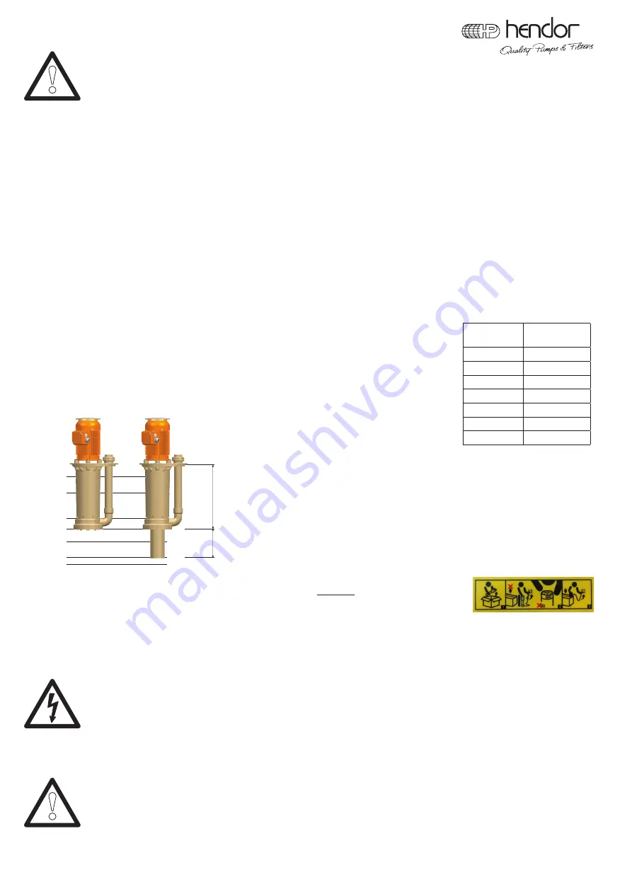
4.1  Vertical pumps

4.1.1 Installation

Take notice of enough bottom clearance at the suction side of vertical pumps.

See recommendations for bottom clearance. 

Hendor vertical pumps are designed for in-tank installation.

Out-of-tank models are optional and require special installation instructions.

Ensure that the pump is connected correct to the power supply and 

that the plumbing is fitted leakfree.


1  maximum liquid level


2  normal working level


3  minimum starting level


4  pump A stops pumping


5  pump B will continue to work


(if it is not switched off)


6  pump B stops pumping


              7 bottom 

tank

4.1.2  Operation and maintenance

At start up the pump should be 

checked for direction of rotation OUTSIDE

 the liquid (see label on pump).

Contaminated strainers (if mounted) can reduce performance and should be cleaned regularly.

Regular pump inspection 

During operation all pumps should be checked regularly. Check flow, pressure, manometer indication, pipe work, hoses, hose clamps and 

absorbed power by monitoring amperage of the motor. Pumps should be fitted with thermal overload switch. Check pumps for any unusual 

noise or vibration (this may indicate the moment of maintenance).


Maintenance precautions 


To avoid dangerous or fatal electric shock hazard and to avoid injury from starting the motor unexpectedly, disconnect and lock


out power supply to the motor. Always use genuine parts to assure good performance. When taking pump apart check for


sequence of disassembly and reassembly. After having completed maintenance or repair, follow safety and installation

 instructions. 

4.1.3  Dismantling and reassembly


  For efficient maintenance of Hendor vertical pumps, some

 special tools

 are available (see page 5).


  General precautions prior to dismantling


-  always disconnect electric cables.


-  disconnect discharge pipe.


-  clean pump and remove remaining liquid in pump housing.


-  do work on a clean bench.


When ordering Hendor parts always quote 

serial number, pump type

 and 

drawing position number of the required part

.

!

Type

Minimum bottom 

distance (mm)

D90

50

D110

55

D120

55

D160

25..100

D18

65

D20

100

D24

100

Immersion

length

(mm)

Suction

extension

B

A

1

2

3
4

5

6

7

max.

min.

Summary of Contents for D110 Series

Page 1: ...s can be electrically charged by its usage This can cause a local burn or even an injury by falling When operating the product make sure it is connected correctly Check grounding and fuses for correct operation When applying maintenance make sure the product is disconnected from the power grid and static discharged Liquids This product is intended to use in liquids of chemical nature Be aware of p...

Page 2: ... failure to ground can cause severe or fatal shock Do not ground to gas supply lines 3 Before connecting the motor check corresponding voltage of motor and power supply Incorrect connection can cause fire or serious damage to the motor and voids warranty See wiring diagram 4 Check if frequency of power supply corresponds with frequency on label of pump 5 Avoid unexpected or accidental starting of ...

Page 3: ...ed correct to the power supply and that the plumbing is fitted leakfree 1 maximum liquid level 2 normal working level 3 minimum starting level 4 pump A stops pumping 5 pump B will continue to work if it is not switched off 6 pump B stops pumping 7 bottom tank 4 1 2 Operation and maintenance At start up the pump should be checked for direction of rotation OUTSIDE the liquid see label on pump Contam...

Page 4: ...cure shaft end against rotation and remove impeller turning anti clockwise with impeller key unscrew 6 screws that are accessible for removing pump house take off pump house loosen shaft protection pipe turning anti clockwise Series D160 remove drip cover if applicable remove fan cover remove cooling fan by applying two screwdrivers remove sealing ring and locking ring turn pump upside down remove...

Page 5: ...kwise viewed from top of the motor Testing the rotation of the shaft has to be done outside the liquid running the pump backwards may loosen the impeller and damage the pump Special tools Tool For disassembly of Use Pump type Article number 1 Strap wrench Suction extension pipe Strap wrench All types 9999 000 000 037 if applicable 2 Grip Strainer if applicable Flat strainer Grip D18 9011 000 001 4...

Page 6: ...ng and NPSH calculation 4 2 2 Operation and maintenance Magnetic drive pumps How it works Driver motor and impeller driven are physically separated by a shell Pump part wet end is completely sealed and therefore isolated from plating proces Power transmission is established by magnetic force between motor shaft and impeller Bearings are lubricated and cooled by liquid itself Mechanical seal pumps ...

Page 7: ...mended maintenance schedule depends upon the nature of the fluid being pumped and the specific application If the pump is used in a clean fluid it is recommended that the pump be removed from service and examined after six months of operation or after 1500 hours of operation If the pump is used on fluids with solids high temperatures or other items that could cause accelerated wear then this initi...

Page 8: ...n of key ensure that drive magnet goes up to shaft end when using a hammer be sure motor bearings are not damaged secure hex screws Assembly mount impeller shell check for free rotation by hand put impeller into shell mind strong magnetic force place O ring and put pump casing into place outlet up mount bolts and tighten them crosswise After assembly always check for free rotation by hand Verify d...

Page 9: ...in filter chamber The maximum pressure in Hendor filter chamber should not exceed the engraved value on top of the cover plate Pressure gauge A pressure gauge is fitted on most Hendor filter chambers An anti freeze filled chamber above a membrane separates the pressure gauge from the process liquid During normal operation the filter chamber regularly should be inspected for flow dial indication on...

Page 10: ...es not take place immediately after delivery the aforementioned warranty period is extended with the duration of the transport it being understood that the warranty period in no case will be longer than 18 months from the delivery ex factory After expiry of this term any warranty becomes void Hendor is not liable and offers no warranty for defects that are not caused by manufacturing and or materi...

Page 11: ... gravity of liquid too high 3 Leak in suction pipe 30 Viscosity of liquid too high 4 Suction pipe or strainer blocked 31 Air gas in liquid 5 Suction height too high 32 Abrasive particles in liquid 6 Air supply close to suction inlet 33 Colloïdal liquid 7 Foot valve or suction pipe insufficiently submerged 34 Liquid temperature too high 8 Valve in pipework partly closed 9 Discharge pipe under tensi...

Page 12: ...6 Discharge pipe 207 Shaft protection pipe 208 Discharge elbow 209 Mounting plate 211 Electric motor 211A Cooling fan 211B Cooling fan cover 213 Suction extension pipe 216 Fastener kit 218 Motor drip cover 730 Union nut 731 Union end 732 O ring Series D110 PP 218 211B 211A 211 201 202 208 732 731 730 207 216 204 203 213 206 218 211B 211A 211 224 201 204 202 733 732 731 730 207 212 202 213 732 731 ...

Page 13: ...lute 202 Volute cover 203 Strainer 204 Impeller 206 Discharge pipe 208 Discharge elbow 209 Mounting plate 211 Electric motor 211A Cooling fan 211B Cooling fan cover 213 Suction extension 216 Fastener kit motor 219 Fastener kit flange 225 Fastener kit impeller 730 Union nut 731 Union end 732 O ring 734 O ring model with vapour lock 204 Impeller 209 Mounting plate 227 Vapour lock impeller 228 Vapour...

Page 14: ...ng 114 Impeller housing 115 Bracket 117 Drive magnet 119 Fastener kit 100A Pump without motor 100B Wet end 100C Impeller complete 111 Electric motor 111A Cooling fan 111B Cooling fan cover 720 Union nut 721 Union end 722 O ring 723 Adapter 724 O ring 730 Union nut 731 Union end 732 O ring 733 Adapter 734 O ring 101 Volute 104 Impeller 105 O ring 106 Shaft 113 O ring PVDF only 114 Impeller housing ...

Page 15: ... ring Series MX160 MX210 MX260 MX350 MX410 PP 101 Volute 104 Impeller 105 O ring 107 Impeller front bearing 108 Impeller rear bearing 114 Impeller housing 115 Bracket 117 Drive magnet 119 Fastener kit 100A Pump without motor 100B Wet end 100C Impeller complete 111 Electric motor 111A Cooling fan 111B Cooling fan cover 720 Union nut 721 Union end 722 O ring 730 Union nut 731 Union end 732 O ring 10...

Page 16: ...ard 720 Union nut 721 Union end 722 O ring 730 Union nut 731 Union end 732 O ring 110 104 100C 119 103 105 100B 100A 126 111 125 101 Volute 102 SS plate 103 Bracket 104 Impeller 105 O ring 109 Rotary seat 110 Stationary seat 109 102 121 122 105 123 124 120 722 730 720 721 732 731 111B 111A 100A Pump without motor 100B Wet end 100C Impeller complete 111 Electric motor 111A Cooling fan 111B Cooling ...

Page 17: ...ension bushing 403 Knob support rod 701 Connection 702 Connection 704 Connection 730 Union nut 731 Union end 732 O ring 11 12 K PP 320 329 321 310 302 Filter housing 305 Chassis 310 O ring 314 Fastener kit 320 Gasket 321 Cover 329 Air release valve 339 O ring 361 Seal plug 375 O ring kit all O rings 401 Support rod 402 Extension bushing 403 Knob support rod 600 Pipe work discharge 701 Connection 7...

Page 18: ...8 327 702 500 701 335 303 340 305 401 325 410 401 302 405 402 407 401 329 334 321 320 319 317 304 403 411 409 408 404 400 350 403 405 404 302 Filter housing 303 Bottom ring 304 Top ring 305 Chassis 317 Rod 319 Star knob 320 Gasket 321 Cover 325 Gauge housing 326 Membrane 327 Cover gauge housing 328 Pressure gauge 329 Air release valve 334 O ring 335 O ring 340 Slurry tank 350 Assembly pressure gau...

Page 19: ...harge 701 Connection 702 Connection 406B Hendor Quality Pumps Filters 19 Info 2016715 R0 406A 326 328 327 702 301 701 335 303 401 410 401 302 405 402 406 407 401 329 334 321 320 319 317 304 411 409 408 404 400 350 405 404 301 Mounting plate 302 Filter housing 303 Bottom ring 304 Top ring 317 Rod 319 Star knob 320 Gasket 321 Cover 325 Gauge housing 326 Membrane 327 Cover gauge housing 328 Pressure ...

Page 20: ...essure gauge 329 Air release valve 334 O ring 335 O ring 350 Assembly pressure gauge 375 O ring kit all O rings 404 O ring 412 Inner cylinder 413 Basket 414 Sealing 701 Connection 702 Connection 703 Connection 326 328 327 702 301 335 413 325 302 412 404 329 334 320 319 317 304 414 321 350 703in 703out Hendor Quality Pumps Filters 20 Info 2016715 R0 F 71 72A B PP 701 303 ...

Page 21: ...Hendor Quality Pumps Filters 21 Info 2016715 R0 302 Filter housing 303 Bottom ring 304 Top ring 305 Chassis 317 Rod 319 Star knob 320 Gasket 321 Cover 325 Gauge housing 326 Membrane 327 Cover gauge housing 328 Pressure gauge 329 Air release valve 334 O ring 335 O ring 340 Slurry tank 350 Assembly pressure gauge 375 O ring kit all O rings 400 Filter element 401 Support rod 402 Extension bushing 403...

Page 22: ...7 304 403 415 409 404 400 350 405 404 322 323 331 416 306 340 324 Hendor Quality Pumps Filters 22 Info 2016715 R0 302 Filter housing 303 Bottom ring 304 Top ring 306 Chassis 317 Rod 319 Star knob 320 Gasket 321 Cover 322 Tilt stop 323 Handle 324 Wheel set 325 Gauge housing 326 Membrane 327 Cover gauge housing 328 Pressure gauge 329 Air release valve 331 Tilting set 332 O ring 334 O ring 335 O ring...

Reviews: