Quick Installation Guide
Document
WERA4-Quick-US-200917
Page 62 of 73
This software tool got a graphical user interface, giving the operator a fast and easy
overview of hardware status, system performance and service/maintenance
information.
The software can either be operated sitting in front of the WERA system on-site, or
remotely by logging in to the graphical user interface via internet remote access.
Software like NX NoMachine, TeamViewer, OpenVPN or similar may be used for this
purpose.
This document contains an overview of the configuration possibilities of this software
tool.
WERA Remote-Control V3.xx may only be used in combination with a WERA system
equipped with a power supply rack with hardware version 4.0 or later. If you got an
earlier hardware version of the power supply rack, you may use V2.6 of the software.
7.10.1.1 WERA Remote-Control-Window
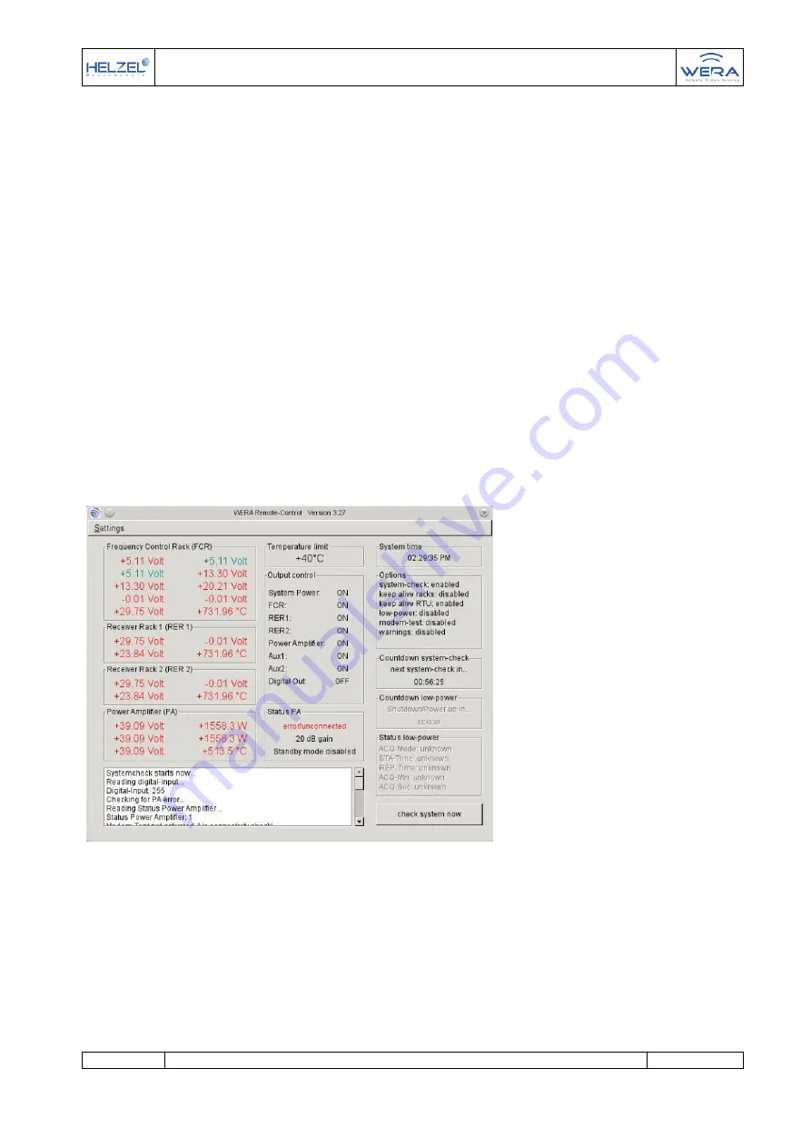
The “WERA Remote-Control-Window” is the main window of the whole program. For
the operator the actual system voltages, WERA power status, clock and additional
options are displayed here. Please have a look at following list to get further details.
Figure: 1 main window
You can see the actual measured supply-voltages of each used rack (FCR - frequency
control rack, RER1 - receiver rack 1, RER2
– receiver rack 2) and the temperature in
degrees inside each rack. If a newer version of the power amplifier (PA) is connected,
the voltages, temperature and forward and reverse power at the output can also be
displayed, as well as the set overall gain of the power amplifier (PA), or if the power
amplifier (PA) has ben set to standby mode or if the automatic self-protection circuit
got triggered.


