


TB20, strain gauge weighing module | Edition 1 | 21.12.2018
46
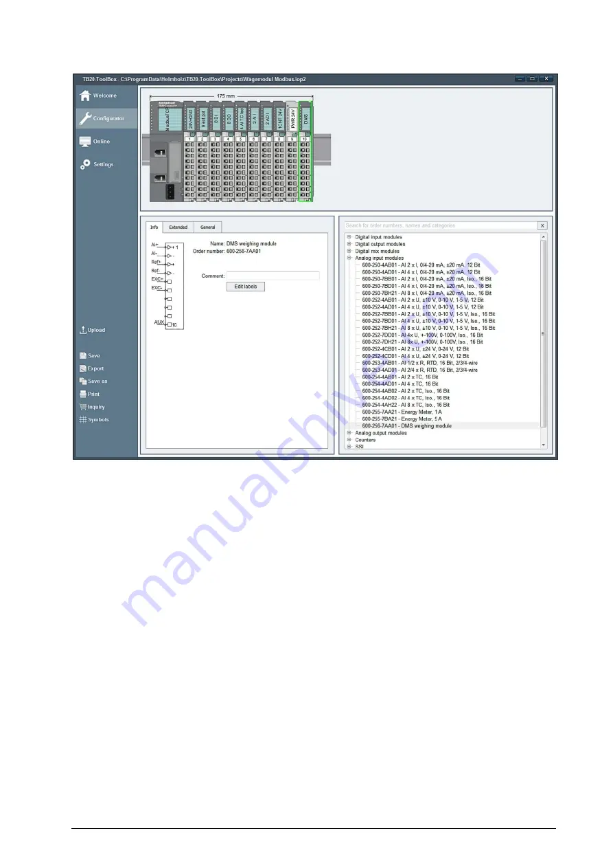
6.3
Configuration with the TB20 ToolBox
In the TB20-ToolBox, positioning and configuration of the modules for the planning of a system is
possible.
The weighing module is configured via the user program of the bus master (PLC) when using the
following couplers:
PROFIBUS-DP
PROFINET IO
See chapter Fehler! Verweisquelle konnte nicht gefunden werden..
The weighing module is configured using the TB20 ToolBox when using the following couplers:
CANopen
Ethernet/IP
ModbusTCP
EtherCAT
DeviceNet


