background image

TT4000 Series 

Operating Instruction 


11 


Operating panel 

The user can control the operation of the printer with the operating panel, for example: 

• 

pause, continue or cancel print jobs 

• 

set printing parameters, e.g. heating energy of the print head, print speed, configuration 
of the ports, language and time (see “

Configuration Instructions

“) 

• 

start test functions (see “

Configuration Instructions

“) 

• 

control standalone operation with memory card (see “

Configuration Instructions

“) 

• 

perform a firmware update (see “

Configuration Instructions

“) 


Several functions and settings can also be controlled via printer-specific commands with 
software applications or via direct programming with a computer. Details on this can be 
found in the “

Configuration Instructions

“. 

The settings made at the operating panel are the basic settings of the label printer. 


It is easier to make adjustments for different print jobs in the software whenever possible. 


4.1 

Layout of the operating panel 


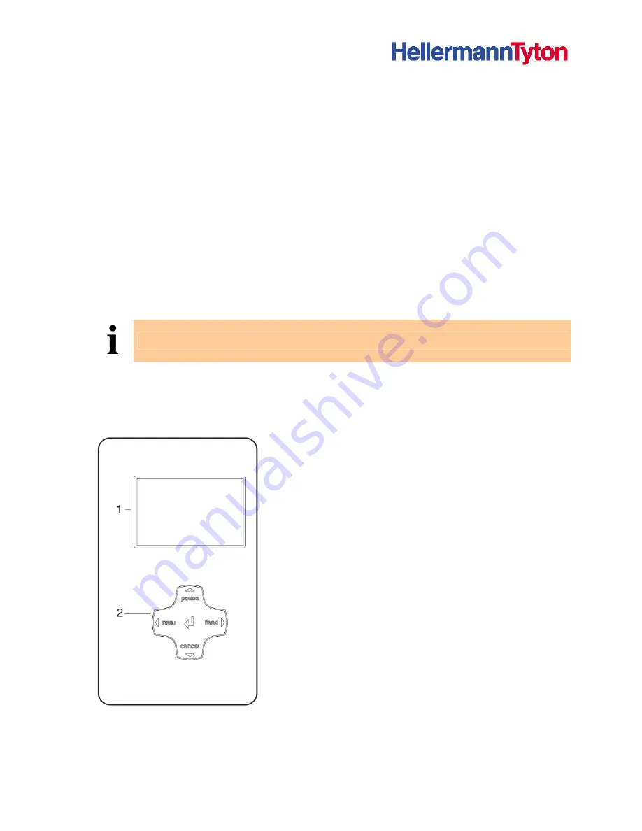
The operating panel is comprised of the graphical display 
(1) and the navigator pad (2) with five integrated buttons. 

The graphical display informs you of the current status of 
the printer and the print job, reports errors and shows the 
printer settings in the menu. 

The button functions are dependent on the current printer 
status: Active functions are indicated by the illuminated 
letters and symbols on the buttons of the navigator pad. 

While printing, active functions illuminate white (e.g. menu 
or feed). Active functions are illuminated in orange in the 
offline menu (arrows, 


Functions of the buttons


pause, cancel, menu, feed buttons: (see 4.2.2 on page 13)  

Arrows: Up, down, left and right in the menu tree.  


button: Input of a parameter in the menu, calling up of 

help in case of an error 


Figure 3 

Operating panel


Summary of Contents for TT4000 Series

Page 1: ...07 HellermannTyton Please check our home page for your nearest sales office Internet http www hellermanntyton com Information on the scope of delivery appearance performance dimensions and weight refl...

Page 2: ...g to the power supply 9 3 3 2 Connecting to a computer or computer network 10 3 4 Switching the label printer on and off 10 4 Operating panel 11 4 1 Layout of the operating panel 11 4 2 Functions of t...

Page 3: ...Printing 26 7 1 Synchronization 26 7 2 Tear Off mode 26 7 3 Peel Off mode Option 26 7 4 Internal rewinding Option 26 8 Cleaning and basic maintenance 27 8 1 Maintenance plan 27 8 2 Tools and cleaning...

Page 4: ...nter 1 2 Warnings notes and other identifying markings 1 2 1 Warnings Warnings are presented with three signal words for the different levels of danger The signal word DANGER identifies an extraordina...

Page 5: ...1 3 Cross references and references to graphics tables and documents 1 3 1 Item numbers Item numbers in the text are identified with parentheses e g 9 If no figure number is provided item numbers in t...

Page 6: ...he manufacturer supplier is not liable for damage resulting from misuse Any misuse is at your own risk Intended use includes heeding the operating instructions including the maintenance recommendation...

Page 7: ...y from other waste i e via an appropriate collection site The modular nature of the label printer allows it to easily be disassembled into its component parts so that the parts can be turned in for re...

Page 8: ...unted on ribbon take up hub Tear off plate Power cable Documentation and driver on CD Retain the original packaging for subsequent transport 3 2 Setting up the label printer CAUTION The device and the...

Page 9: ...nd computer connections 3 3 1 Connecting to the power supply The printer is equipped with a versatile power supply unit The device may be operated with a mains voltage of 230 V AC 50 Hz or 115 V AC 60...

Page 10: ...uter or network with a suitable cable Details on the configuration of the individual interfaces are found in the Configuration Instructions 3 4 Switching the label printer on and off Once all connecti...

Page 11: ...nel are the basic settings of the label printer It is easier to make adjustments for different print jobs in the software whenever possible 4 1 Layout of the operating panel The operating panel is com...

Page 12: ...e For configuration of the status line see the Configuration Instructions Symbol Meaning Time Date Ribbon supply status WLAN field strength Ethernet status Print head temperature PPP credit User memor...

Page 13: ...int job is possible in Printing mode The new print job starts once the preceding job is completed The display shows the text Printing Label and the number of the printed label within the print job But...

Page 14: ...displayed Table 5 Functions in error which can be remedied mode 4 2 6 Fault irrecoverable mode An error that cannot be remedied without cancelling the print job has occurred The display shows the symb...

Page 15: ...d shrinking sleeve can be cut off automatically with the Cutter S3000 accessory For details see HellermannTyton product catalogue The accessory Perforator P3000 enables the printer to automatically pe...

Page 16: ...ding labels from a roll 1 Open cover 10 2 Loosen knurled screw 1 and swivel guide 2 upward and push it all the way out 3 Load label roll on the roll retainer in such a way that the labels can be inser...

Page 17: ...against the outer edge of the label strip 6 1 3 Setting the label sensor Figure 5 Setting the label sensor The label sensor 2 can be shifted perpendicular to the direction of paper flow for adaptatio...

Page 18: ...tional In Rewind mode the labels are wound up internally after printing for later use 1 Remove the locking system for Rewind mode if necessary see 6 7 on page 25 and install rewind guide plate see 6 6...

Page 19: ...nd assist roller 5 4 Hold rewinder 2 firmly and turn knob 3 clockwise until it stops 5 Push liner under a bracket 1 of the rewinder 2 and turn knob 3 anti clockwise until it stops The rewinder is full...

Page 20: ...to achieve even print quality across the entire label width prevent wrinkles in the feed path of the transfer ribbon prevent premature wearing of the print roller and print head Figure 8 Setting the h...

Page 21: ...oving the wound roll 1 Turn lever 7 anti clockwise to lift the print head 2 Cut label strip and wind it fully around the rewinder 2 3 Hold rewinder 2 firmly and turn knob 3 clockwise The rewinder spin...

Page 22: ...4 behind the printer Ensure that the labels on the strip are visible from above 3 Guide label strip to print unit via the roll retainer 3 See Figure 10 4 Push guide 2 against the label strip swivel it...

Page 23: ...secured 5 Slide suitable transfer ribbon core onto the transfer ribbon take up hub 1 and secure it in the same way 6 Guide transfer ribbon through the print unit as shown in Figure 11 7 Secure startin...

Page 24: ...e dispense plate or tear off plate To convert the printer for use in another operating mode a rewind guide plate a dispense plate or a tear off plate may need to be installed For printer versions with...

Page 25: ...ew out screws 1 2 and remove them 3 Remove the pinch roller 4 and bottom plate 3 Installing the locking system 1 Position printer at edge of table so that the oblong hole is accessible from below 2 Pl...

Page 26: ...y 1 Press the feed button to start synchronization 2 Remove empty labels after synchronization The printer is synchronized with the loaded label medium Synchronization is not necessary if the print he...

Page 27: ...ansfer printing each time the transfer ribbon is changed or when the print image is adversely affected Clean label sensor see 8 6 on page 29 when the label roll is changed Replace print head see 8 7 o...

Page 28: ...h roller cleaner and a soft cloth 4 If the roller appears damaged replace it see 8 8 on page 32 8 5 Cleaning the print head Substances may accumulate on the print head during printing and adversely af...

Page 29: ...head 2 Remove labels and transfer ribbon from the printer 3 Remove hexagonal wrench 5 from its retainer 4 Press the latch 3 and slowly pull label sensor outward via the tab 4 Ensure that this does not...

Page 30: ...ead plate 2 Plug connection 3 Plug connection 4 Screw 5 Printing line 6 Pins 7 Print head Figure 16 Structure of the print head The print head 8 is preinstalled on a head plate 1 and precisely aligned...

Page 31: ...6 Remove print head from the print head mounting bracket 9 if necessary 7 Loosen both plug connections 2 3 on the print head and set print head down on a clean soft surface Installing the print head 1...

Page 32: ...Removing the side plate Removing and installing rollers 1 Pull print roller 7 and rewind assist roller 8 from the shafts 9 10 on the housing 2 Clean shafts 9 10 of the rollers see expanded view at sha...

Page 33: ...rinter remove sideplate of printer on supply hub shaft adjust green coloured knob to lower number Too little tension Disconnect printer remove sideplate of printer on supply hub shaft adjust green col...

Page 34: ...he label roll on the roll retainer on page 16 and Setting the label sensor on page 17 Print driver settings Open print driver Properties Options Unprintable area ensure both left and right are set to...

Page 35: ...r driver is allocated to the correct USB port Alternatively remove printer driver and reinstall new Table 9 Troubleshooting 9 3 Error messages and recovery Error message Cause Error recovery ADC malfu...

Page 36: ...Several labels are missing from the label strip Press the pause button several times until the next label on the strip is detected by the printer The label format specified in the software does not m...

Page 37: ...ress the pause button to skip the command or Press the cancel button to cancel the print job Read error Read error when accessing memory card Check data on memory card Save data Reformat card Structur...

Reviews: