background image

be necessary to directly connect input and output 

ground or to tie both grounds together via a resistor. 

Therefore the 

Ground lift switch

 has three positions:

 center 

position: input and output ground 

 separated.

-   left position: input and output ground tied 

 together.

 right 

position: input and output ground 

 connected via 200 Ohms resistor.

8

  Control pushbutton

The 

Control pushbutton

 allows the user to switch 

between the two setup memory positions. To switch 

between the setups the button has to be pressed 

and held for one second. Switching is indicated by 

a single red flash of the 

Status LED

. Pressing the 

button for five seconds completely eras es the inter

-

nal memory. This is indicated by a constant flashing 

of the 

Status LED

.

Attention: 

After erasing the setups from memory 

the HELIX DSP PRO MK2 will not reproduce any 

audio output.

9

  Status LED

The 

Status LED

 indicates the current active DSP 

setup. Green means that setup 1 is load ed, orange 

means that setup 2 is loaded. A flashing red light in

-

dicates that no setup is loaded. In that case please 

load a new setup via the DSP PC-Tool software. If 

the LED starts blinking orange, the internal tem-

perature protection is active. At first the remote out

-

put will be turned off. If the temperature still rises the 

signal processor will shut down until it has reached 

a safe temperature level again.

10

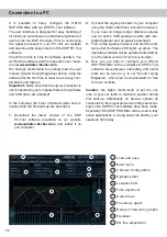
  USB input

Connect your personal computer to the 

DSP PRO MK2 using the provided USB cable. 

The  required  PC  software  to  configure  this  signal 

processor can be downloaded from the Audiotec 

 Fischer  website 

www.audiotec-fischer.com

Please note:

 It is not possible to connect any USB 

storage devices. 

11

  Control Input

This multi-functional input is designed for HELIX ac-

cessory products like a remote control which allows 

to adjust several features of the signal processor. 

Depending on the type of remote control, at first its 

functionality has to be defined in the “ Device Con

-

figuration Menu” of the DSP PC-Tool software.

12

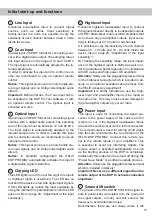
  Line Output

10-channel  pre-amplifier  output  for  connecting 

 po wer amplifiers. The output voltage is 8 Volts max. 

Please make sure that you always turn on/off exter-

nal amplifiers using the remote output of the signal 

processors 

Power Input

. Never directly control the 

external amps by a signal from the ignition switch 

of your car! Additionally this output will be turned 

off when the “Power Save Mode” of the signal pro-

cessor is active. The outputs can be assigned to 

any of the inputs as desired using the DSP PC-Tool 

software.

18

Initial start-up and functions

Summary of Contents for DSP PRO MK2

Page 1: ...Digitaler High Res 10 Kanal Signalprozessor mit 96 kHz 32 Bit Signalweg Digital High Res 10 channel signal processor with 96 kHz 32 Bit signal path deutsch english DSP PRO MK2 ...

Page 2: ...r elektronischen Steuerungen des Fahrzeuges Im Sinne der Unfallsicherheit muss der Signalprozessor professionell befestigt werden Dieses geschieht über Schrauben die in eine Mon tagefläche eingeschraubt werden die wiederum genügend Halt bieten muss Bevor Sie die Schrauben im Montagefeld befesti gen vergewissern Sie sich dass keine elektrischen Kabel und Komponenten hydraulische Bremslei tungen der...

Page 3: ...schluss des der Verstärker s Zur Einschaltung eines angeschlossenen Verstärkers muss der Remote Ausgang verwendet werden 1 Line Input Cinch Eingänge zum Anschluss eines Vorverstärkersignals 2 Coax Input Elektrischer Eingang im SPDIF Format für digitale Stereosignale 3 Optical Input Optischer Eingang im SPDIF Format für digitale Stereosignale 4 Clipping LED Diese LED leuchtet rot wenn einer der Ana...

Page 4: ...gangsempfindlichkeit über die internen Trimmer siehe Seite 7 Einstellung der Eingangs empfindlichkeit abgesenkt werden bis die LED erlischt 5 Highlevel Input 8 Kanal Hochpegel Lautsprechereingang Mit Hilfe dieses Eingangs kann der Prozessor direkt an die Lautsprecherausgänge eines Werks Nachrüst radios oder eines Werksverstärkers angeschlos sen werden sofern dieses dieser nicht über Vorverstärkera...

Page 5: ...ist Setup 1 geladen Bei Setup 2 leuch tet die LED orange Sollte sich kein Setup im inter nen Speicher befinden blinkt die LED rot Sofern letzteres der Fall ist muss über die DSP PC Tool Software ein neues DSP Setup eingespielt werden Sollte die LED orange blinken so ist die Sicher heitsschaltung der Temperaturüberwachung aktiv Im ersten Schritt wird nun der Remote Ausgang abgeschaltet Sollte die T...

Page 6: ...sempfindlichkeit der Highlevel Eingänge Jumper oben Jumper unten 2 V 4 V 5 V 10 V Cinch 2 V 4 V Hochpegel 10 V 20 V Justierung der Eingangsempfindlichkeit für die Nutzung der Kanäle G H als AUX Eingang Jumper unten Kanal G H 2 V 4 V Jumper oben Kanal G H 250 mV 500 mV Abb 1 Abb 2 Abb 3 Auslieferungszustand des HELIX DSP PRO MK2 ...

Page 7: ...endung dieses Eingangs muss der Remote Eingang nicht belegt werden da sich der Signalprozessor automatisch einschaltet sobald ein Lautsprechersignal anliegt 3 Einstellung der Eingangsempfindlichkeit Achtung Es ist zwingend notwendig die Eingangsempfindlichkeit des DSP PRO MK2 an die Signalquelle anzupassen um Schä den am Signalprozessor zu vermeiden Um die Eingangsempfindlichkeit ändern zu können ...

Page 8: ... möglich Wichtig Das digitale Audiosignal einer Quelle ist üblicherweise nicht lautstärkegeregelt Das bedeutet dass an den Signalausgängen des HELIX DSP PRO MK2 der volle Pegel anliegt und die angeschlossenen Verstärker voll aus gesteuert werden Dies kann im Extremfall die Lautsprecher zerstören Wir raten deshalb dringend dazu eine optionale Fernbedienung zur Einstellung der Lautstärke der digital...

Page 9: ...ote Schalters geändert wer den Dazu entfernen Sie bitte das Seitenblech der Geräteseite mit dem USB Eingang indem Sie die fünf Kreuzschlitzschrauben lösen Nun können Sie das Bodenblech aus dem Kühl körper zur Seite hinausziehen und erhalten so Zugriff auf den Schalter Dieser befindet sich in der Nähe des Jumpers zur Änderung der Ein gangsempfindlichkeit der Highlevel Eingänge siehe Markierung im n...

Page 10: ... des DSPs 4 Beim Anschluss der Stromversorgung muss fol gendes noch beachtet werden Je nach Fahrzeugtyp können die Anschlüsse für Zündplus und Dauerplus vertauscht sein Der DSP sollte die Stromversorgung jedoch nicht über die Zündleitung beziehen da es sonst zu Störgeräuschen kommen kann Aus diesem Grund muss vor der endgültigen Inbe triebnahme die Zuordnung von Zündplus und Dauerplus an der roten...

Page 11: ...ieb nahme 1 Laden Sie die DSP PC Tool Software unter www audiotec fischer com herunter und in stallieren diese auf ihrem Computer 2 Schließen Sie danach den DSP PRO MK2 mit dem beiliegenden USB Kabel an den Compu ter an Wenn Sie längere Distanzen zu über brücken haben verwenden Sie bitte eine aktive USB Verlängerung mit integriertem Repeater und kein passives USB Kabel 3 Schalten Sie erst den Sign...

Page 12: ...2 Lösen Sie die fünf Kreuzschlitzschrauben des Seitenblechs der Geräteseite mit dem USB Ein gang und entfernen dieses 3 Ziehen Sie nun das Bodenblech zur Seite he raus 4 Bereiten Sie das Modul für den Einbau in das Gerät vor Informationen dazu entnehmen Sie bitte der Bedienungsanleitung des jeweiligen HEC Moduls 5 Stecken Sie das HEC Modul in den im Gerät vorgesehenen Sockel siehe Markierung im na...

Page 13: ...t Das Netzteil im HELIX DSP PRO MK2 stellt die in terne Spannungsversorgung auch bei kurzfristigen Einbrüchen bis hinab zu 6 Volt sicher Damit ist gewährleistet dass der HELIX DSP PRO MK2 auch beim Motorstart voll funkti onsfähig bleibt Power Save Modus Der Power Save Modus ist in den Grundeinstel lungen der DSP PC Tool Software aktiviert Er er laubt die Leistungsaufnahme der an den Signal prozess...

Page 14: ...mA Zusätzliche Features HEC Slot Masseschalter Control Input ADEP Schaltkreis Auto Remote Schalter Abmessungen H x B x T 40 x 177 x 150 mm Technische Daten Garantiehinweis Die Garantieleistung entspricht der gesetzlichen Regelung Von der Garantieleistung ausgeschlos sen sind Defekte und Schäden die durch Überla stung oder unsachgemäße Behandlung entstanden sind Eine Rücksendung kann nur nach vorhe...

Page 15: ...installa tion location to insure that there are no electrical cables or components hydraulic brake lines or any part of the fuel tank located behind the mounting surface Failure to do so may result in unpredictable damage to these components and possible costly repairs to the vehicle General instruction for connecting the HELIX DSP PRO MK2 signal processor The HELIX DSP PRO MK2 signal processor ma...

Page 16: ...ther HELIX accessory 12 Line Output Line outputs for connecting amplifiers Make sure that the remote output is used to turn on these devices 1 Line Input RCA inputs for connecting pre amplifier signals 2 Coax Input Electrical input for digital stereo signals SPDIF format 3 Optical Input Optical input for digital stereo signals SPDIF format 4 Clipping LED This LED lights up red if one of the analog...

Page 17: ... processor directly to loudspeaker outputs of OEM aftermarket radios or OEM amplifiers that do not have any pre amplifier outputs Input sensi tivity is factory set to 10 Volts for all channels It is possible to vary the sensitivity of each channel between 5 10 Volts and 10 20 Volts inside the device item 3 page 20 Adjustment of the input sensitivity By changing the sensitivity range the input impe...

Page 18: ...ion is active At first the remote out put will be turned off If the temperature still rises the signal processor will shut down until it has reached a safe temperature level again 10 USB input Connect your personal computer to the DSP PRO MK2 using the provided USB cable The required PC software to configure this signal processor can be downloaded from the Audiotec Fischer website www audiotec fis...

Page 19: ...evel inputs Jumper upper position Jumper lower position 2 V 4 V 5 V 10 V RCA Cinch 2 V 4 V Highlevel 10 V 20 V Adjustment of the input sensitivity for using channel G H as AUX inputs Jumper lower position Channel G H 2 V 4 V Jumper upper position Channel G H 250 mV 500 mV 19 Installation Ex factory adjustment of HELIX DSP PRO MK2 Fig 1 Fig 3 Fig 2 ...

Page 20: ...turn on once a loudspeaker signal is received 3 Adjustment of the input sensitivity Attention It is mandatory to properly adapt the input sensitivity of the DSP PRO MK2 to the signal source in order to avoid damage to the signal processor If you want to change the input sensitivity you have to open the device at first Dismantle the side panel where the USB input is located by removing the five Phi...

Page 21: ...d 96 kHz 192 kHz and no Dolby coded signals 5 Connection to power supply Make sure to disconnect the battery before installing the HELIX DSP PRO MK2 Solely use the included screw type terminal to connect the HELIX DSP PRO MK2 to a pow er supply Make sure of correct polarity The ground wire must be connected to the vehicle chassis at a non insulated point Inadequate grounding causes audible interfe...

Page 22: ...n ducted with the DSP PC Tool software be fore using the signal processor for the first time Ignoring this advice may result in damaging the connected amplifiers the loudspeakers Infor mation about connecting the DSP PRO MK2 to a computer can be found on page 24 9 Connecting the remote output This output Remote out is used to supply re mote signals to the external amplifier s Always use this remot...

Page 23: ...e HELIX DSP PRO MK2 inputs Highlevel Input A to D and Power Input 4 Please note when connecting the power sup ply the permanent and switched 12 Volts wires may be reversed depending on vehicle type The HELIX DSP PRO MK2 should not be plugged into the power supply via the ignition cable as this may cause interferences Before connecting the Easy Plug Cable to the HELIX DSP PRO MK2 verification of th...

Page 24: ...l processor to your computer using the USB cable that is included in delivery If you have to bridge longer distances please use an active USB extension cable with inte grated repeater and no passive extension 3 Turn on the signal processor and start the soft ware after the Status LED lights up green The operating software will be updated automatical ly to the latest version if it is not up to date...

Page 25: ...e the side panel where the USB input is located by removing the five Phillips screws 3 Pull out the bottom plate sideways 4 Prepare the module for installing it into the de vice Any further mounting information will be found in the instruction manual of the respective HEC module 5 Insert the HEC module into the specific slot of the device which is marked in the following picture 6 Make sure that t...

Page 26: ...ems without load ing the speaker outputs of the OE radio during high volumes unnecessarily Start Stop capability The switched power supply of the HELIX DSP PRO MK2 assures a constant internal supply voltage even if the battery s voltage drops to 6 Volts during engine crank Power Save Mode The Power Save Mode is incorporated in the basic setup It allows to significantly reduce the power consumption...

Page 27: ...rrent draw 510 mA Max remote output current 500 mA Additional features HEC slot Ground lift switch Control Input ADEP circuit Auto Remote switch Dimensions H x W x D 40 x 177 x 150 mm 1 58 x 6 97 x 5 91 Technical Data Warranty Disclaimer The limited warranty comply with legal regulations Failures or damages caused by overload or im proper use are not covered by the warranty Please return the defec...

Page 28: ...Audiotec Fischer GmbH Hünegräben 26 57392 Schmallenberg Germany Tel 49 2972 9788 0 Fax 49 2972 9788 88 E mail helix audiotec fischer com Internet www audiotec fischer com ...

Reviews: