background image

TIP!

TIP!

3

Passive house compact units KWL EC 270/370 W R/L

Installation and Operating Instructions

EN

1.12  Technical data

        KWL EC 270 W R/L


Voltage/Frequency

                               1~ 230 V~/50 Hz                 

Connection wiring diagram

      SS-1044


Rated current – ventilation

                    1.0 A                                    

Temperature operating range    

-20 °C to +40 °C

Pre-heater (outlet) kW

                           1.0 kW                                 

Installation kit weight                 

49 kg

Summer bypass

                                   auto 

(adjustable)


Standby losses                         

< 1 W

Electrical power feed to UV 

                 NYM-J 3 x 1.5 mm

2


Protection to

                            IP20

Air flow rates  Vm

3

/h (3 levels)               

285 / 170 / 110                    

Installation area temperature     

+5 °C to +40 °C

        KWL EC 370 W R/L


Voltage/Frequency

                               1~ 230 V~/50 Hz                 

Connection wiring diagram

      SS-1044


Rated current – ventilation

                    2.2 A                                    

Temperature operating range    

-20 °C to 40 °C

Pre-heater (outlet) kW

                           1.0 kW                                 

Installation kit weight                 

52 kg

Summer bypass

                                   auto 

( adjustable)


Standby losses                         

< 1 W

Electrical power feed to UV 

                 NYM-J 3 x 1.5 mm

2


Protection to

                            IP20

Air flow rates  Vm

3

/h (3 levels)               

350 / 200 / 140                    

Installation area temperature     

+5 °C to +40 °C

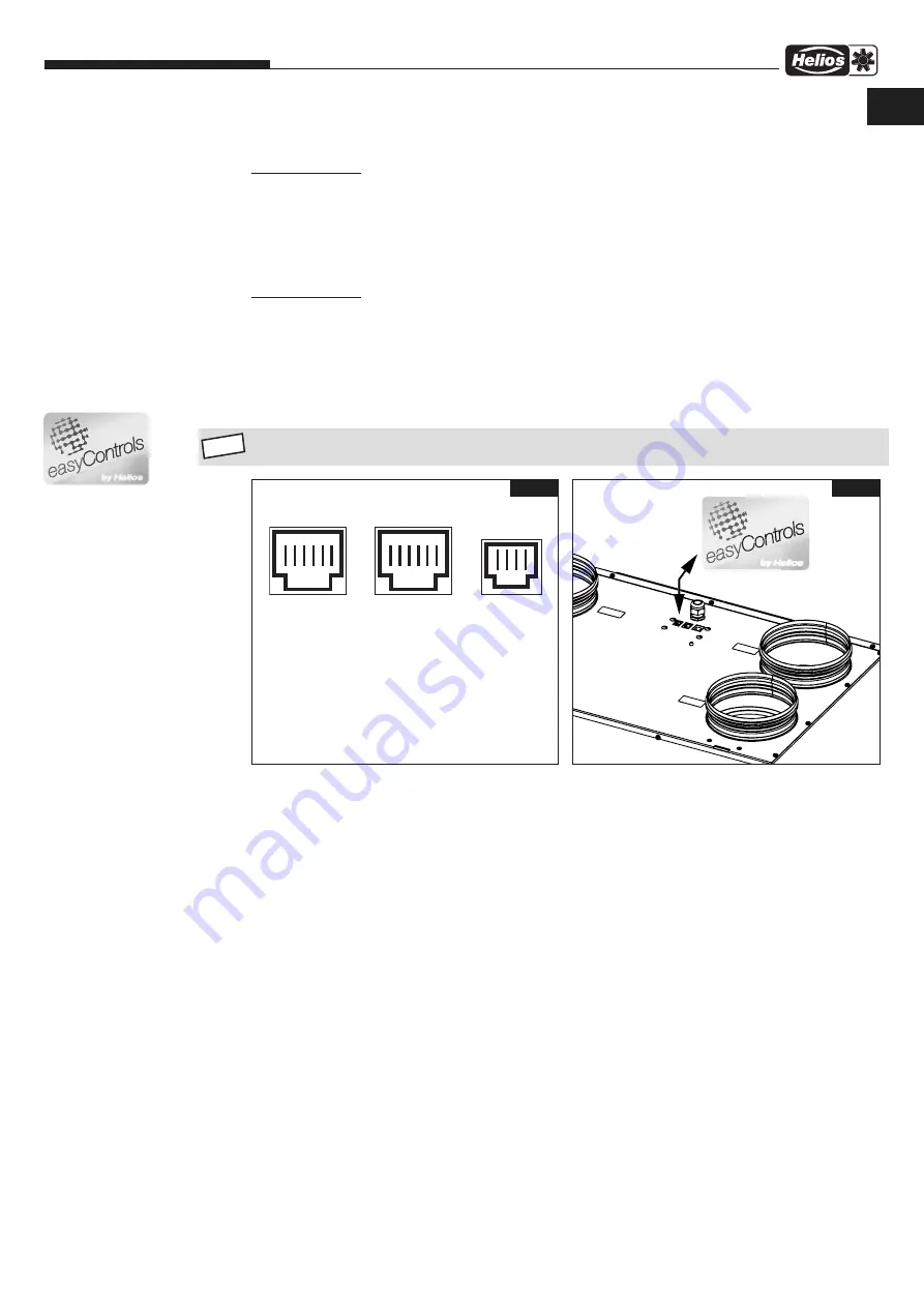
1.13  RJ connections with easyControls

Take note of the information in the “easyControls” user manual (No. 82 200)

RJ12

St

eu

er

le

it

un

RJ

10

 ( 

di

gi

ta

)

RJ45

St

eu

er

le

it

un

RJ

12

 ( 

An

al

og

 )

RJ10

TC

P/

IP

 V

er

bi

nd

un

g

Fig.1

Fig.2

Summary of Contents for KWL EC 270 W L

Page 1: ...Helios Ventilatoren MONTAGE UND BETRIEBSVORSCHRIFT Passivhaus Kompaktger t mit easyControls KWL EC 270 W R L KWL EC 370 W R L W rmer ckgewinnung und EC Technik f r zentrale Be und Entl ftung DE...

Page 2: ...r Seite 10 4 2 Filterwechsel Seite 10 4 3 Kondensatablauf im Ger t Seite 11 4 4 Zugang zum internen Klemmenkasten Seite 11 4 5 Demontage EPS Innenkorpus Seite 11 4 6 Montage EPS Innenkorpus mit Motore...

Page 3: ...ll auftretende Sch den unterliegen nicht der Gew hrleistung Wenn diese Ausf hrungen nicht beachtet werden entf llt unsere Gew hrleistung Gleiches gilt f r Haftungsanspr che an den Hersteller 1 4 Vorsc...

Page 4: ...warme Jahreszeiten ist der Sommer Bypass die optimale L sung um k hlere Au enluft in das Geb ude zu leiten Durch die integrierten Filter wird die Luft optimal gereinigt Dies sorgt f r ein hygienische...

Page 5: ...m3 h 3 Stufen 285 170 110 Temperatur Aufstellbereich 5 C bis 40 C KWL EC 370 W R L Spannung Frequenz 1 230 V 50 Hz Anschluss nach Schaltplan SS 1044 Nennstrom L ftungsbetrieb 2 2 A Temperatur Arbeitsb...

Page 6: ...y CWX CCCCC m w y j FKOGH GI CCCCC CCCCC J CCCCC CCCCC GJ CCCCC CCCCC K c D fhe CCCCC GK CCCCC c amb Y HMF m h y NKKFG amb Y HMFEIMF m h y NKKGJ c amb Y HMF m b NKLMK amb Y HMFEIMF m b NKKGK c amb Y I...

Page 7: ...unktionsschema Abb 17 3 Die Heizung muss so eingebaut sein dass der Elektrokasten leicht zug nglich ist 4 Um Schall bertragungen zu vermeiden muss je nach Bausubstanz bauseits eine geeignete Schallent...

Page 8: ...4 Drehung im Befestigungsteil einrasten Abb 12 HINWEIS Darauf achten dass die Schwimmer Kugel lose im Geh use liegt 6 Kondensatschlauch DN 12 mm L nge max 1 5 m an das Entw sserungssystem des Hauses...

Page 9: ...Anschluss darf nur von einer autorisierten Elektrofachkraft entsprechend den nach stehenden Anschlusspl nen ausgef hrt werden Die einschl gigen Normen Sicherheitsbestimmungen z B DIN VDE 0100 sowie d...

Page 10: ...ehende Brandschutzvorschriften sind unbedingt zu beachten Detaillierte Hinweise zur Einregulierung von KWL Wandger ten sind aus der Montage und Betriebs vorschrift KWL easyControls Erstinbetriebnahme...

Page 11: ...ie t die Bypassklappe vollst ndig Abb 18 Der Bypass wird ge ffnet wenn alle Bedingungen erf llt sind Bedingung 1 Die Ablufttemperatur F hler T3 ist h her als die Bypasstemperatur Bypasstemperatur mind...

Page 12: ...Optional sind zuluft und bypassseitig F7 Filter erh ltlich Abb 22 Bei der Verwendung von F7 Filtern auf die Luftrichtungspfeile auf den Filter Etiketten achten Die Luftrichtung ist auf dem Ger teaufkl...

Page 13: ...linken Au enseite bei linken Ger ten auf der rechten Au enseite 4 5 Demontage EPS Innenkorpus mit Motoreinheit 1 Zur Demontage des EPS Innenkorpus mit Motor und W rmetauschereinheit muss der Frontrah...

Page 14: ...Heizregister KWL CO2 Best Nr 4272 CO2 F hler zur Erfassung der CO2 Konzentration in der Raumluft KWL FTF Best Nr 4273 Feuchte F hler zur Erfassung der Raumluftfeuchte KWL VOC Best Nr 4274 Luftqualit...

Page 15: ...r j QR Produktionscode r EAN Code Art Nr k EAN Code Seriennummer t Leistungsaufnahme P Gebl se f r Ersatzluftfilter Shop www ersatzluftfilter de y Nennstrom A Gebl se im L ftungsbetrieb u Spannungsber...

Page 16: ...Elektro Heizung siehe Warm Wasser Heizung bzw L SEWT siehe Adressierung mit DIP beachten SS 1078 SS 1145 SS 1145 Analog Steuerung 1 4 1 4 1 4 RJ10 RJ10 RJ10 JP JP JP 1 4 1 4 1 4 1 off on 2 DIP DIP DIP...

Page 17: ...ft Motor bl ws ge Steuerung Au en Zuluft Motor bl ws ge frei frei bl ws ge bl ws ge 37 36 35 34 33 32 Bypass bergabeplatine 1 8 1 6 1 4 LAN AnalogDigital 1 8 1 6 1 4 rt gn LED 2 LED 1 gn ge LED 4 LED...

Page 18: ...ypass bergabeplatine 1 8 1 6 1 4 LAN AnalogDigital 1 8 1 6 1 4 rt gn LED 2 LED 1 gn ge LED 4 LED 3 RJ 45 RJ 12 RJ 10 PI N LAN Analog Digital 1 TX 24 5 V I max 0 9 A 24 5 V I max 0 9 A 2 TX 0 10 V Vent...

Page 19: ...htigkeit pr fen b Schwimmer Kugel im Siphongeh use schmutzig oder nicht vorhanden Schwimmer Kugel reinigen bzw einlegen Punkt 2 2 c Siphon verstopft Siphon reinigen d Gef lle nicht vorhanden Installat...

Page 20: ...c Mesnil Cedex CH HELIOS Ventilatoren AG Tannstrasse 4 8112 Otelfingen GB HELIOS Ventilation Systems Ltd 5 Crown Gate Wyncolls Road Severalls Industrial Park A HELIOS Ventilatoren Postfach 854 Siemens...

Page 21: ...Helios Ventilatoren INSTALLATION AND OPERATING INSTRUCTIONS Passive house compact unit with easyControls KWL EC 270 W R L KWL EC 370 W R L Heat recovery and EC technology for central ventilation EN...

Page 22: ...4 3 Condensation outlet in the unit Page 11 4 4 Access to internal terminal box Page 11 4 5 Removal of EPS inner shell Page 11 4 6 Assembly of EPS inner shell with motor unit Page 12 4 7 Other accesso...

Page 23: ...according to easyControls operating instructions The use of accessories which are not approved recommended or offered by Helios is not permissible Any damages are excluded from the guarantee If these...

Page 24: ...ater accessories EHR R or WHR The summer bypass is the optimum solution to conduct cooler outside air into the building during warm periods The air is optimally pre filtered through the integrated fil...

Page 25: ...els 285 170 110 Installation area temperature 5 C to 40 C KWL EC 370 W R L Voltage Frequency 1 230 V 50 Hz Connection wiring diagram SS 1044 Rated current ventilation 2 2 A Temperature operating range...

Page 26: ...JLOK GH y CWX CCCCC m w y j FKOGH GI CCCCC CCCCC J CCCCC CCCCC GJ CCCCC CCCCC K c D fhe CCCCC GK CCCCC c amb Y HMF m h y NKKFG amb Y HMFEIMF m h y NKKGJ c amb Y HMF m b NKLMK amb Y HMFEIMF m b NKKGK c...

Page 27: ...installed in such a way that the electric box is easily accessible 4 In order to avoid sound transmissions a suitable acoustic insulation must be planned on site depending upon the structure 5 When in...

Page 28: ...onnect siphon housing and turn the mounting part a 1 4 turn Fig 12 NOTE Ensure that the floating ball is in the housing 6 Connect the condensation hose DN 12 mm length max 5m to the drainage system on...

Page 29: ...g diagram and are only to be carried out by cer tified electricians All relevant national standards safety regulations and provisions e g DIN EN VDE 0100 and the technical connection conditions of the...

Page 30: ...must be observed Detailed information on the adjustment of KWL wall mounted units can be found in the Installation and Operating Instructions KWL easyControls Initial Commissioning No 82 237 H jJ jI j...

Page 31: ...bypass damper closes completely Fig 18 The bypass is opened when all conditions are met Condition 1 The extract air temperature sensor T3 is higher than the bypass temperature bypass temperature min...

Page 32: ...and bypass filter Fig 20 F7 filters are optional on the supply air and bypass side Fig 22 When using F7 filters pay attention on air flow direction arrows on the filter labels The air flow direction i...

Page 33: ...on right hand units on the outer right side on left hand units 4 5 Removal of EPS inner shell 1 In order to remove the EPS inner shell with motor and heat exchanger unit the front frame must be remove...

Page 34: ...r for heater battery KWL CO2 Ref no 4272 CO2 sensor to detect the CO2 concentration in the room air KWL FTF Ref no 4273 Humidity sensor to detect the room air humidity KWL VOC Ref no 4274 Air quality...

Page 35: ...QR production code r EAN Code Ref no k EAN Code serial number t Power consumption P Fan for replacement filter shop www ersatzluftfilter de y Rated current A fan in ventilation mode u Voltage range V...

Page 36: ...chluss Elektro Heizung siehe Warm Wasser Heizung bzw L SEWT siehe Adressierung mit DIP beachten SS 1078 SS 1145 SS 1145 Analog Steuerung 1 4 1 4 1 4 RJ10 RJ10 RJ10 JP JP JP 1 4 1 4 1 4 1 off on 2 DIP...

Page 37: ...ital 1 8 1 6 1 4 rt gn LED 2 LED 1 gn ge LED 4 LED 3 R J 45 R J 12 R J 10 PI N L A N A nalog D igital 1 T X 24 5 V I max 0 9 A 24 5 V I max 0 9 A 2 T X 0 10 V V entilatorstufe BU S A 3 RX 3 9 5 9 V Of...

Page 38: ...Analog Digital 1 TX 24 5 V I max 0 9 A 24 5 V I max 0 9 A 2 TX 0 10 V Ventilatorstufe BUS A 3 RX 3 9 5 9 V Offset BUS B 4 TC LED rot GND 5 RC LED gr n x 6 RX GND x 7 frei x x 8 GND x x F1 F2 Geh use S...

Page 39: ...on outlet not functioning a Siphon leaking Check for tightness b Floating ball in the siphon housing dirty or non existent Clean or insert floating ball section 2 2 c Siphon clogged Clean siphon d No...

Page 40: ...nil Cedex CH HELIOS Ventilatoren AG Tannstrasse 4 8112 Otelfingen GB HELIOS Ventilation Systems Ltd 5 Crown Gate Wyncolls Road Severalls Industrial Park A HELIOS Ventilatoren Postfach 854 Siemensstra...

Reviews: