HEIDENHAIN EnDat 2.2 Technical Information Download Page 17

17

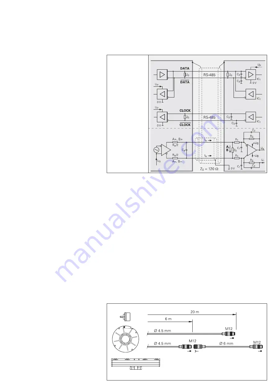
Data (measured values or parameters) can 
be transferred bidirectionally between 
position encoders and subsequent 
electronics with transceiver components in 
accordance with RS-485 (differential 
signals), in synchronism with the clock 
signal (CLOCK) produced by the 
subsequent electronics.

Dimensioning

IC

1

 = RS 485 differential line receiver and 

driver

C

3

  = 330 pF

Z

0

  = 120 

Encoder

Subsequent electronics

Input Circuitry of the Subsequent Electronics

Data transfer

Incremental signals

depending on 
encoder


Connecting elements

For the encoders with EnDat 2.2 interface 
without incremental signals, 8-pin M12 
connecting elements are used. M12 
connector technology is in wide use in 
industrial applications and has the following 
advantages:

Cost-effective connection technology

• 

Smaller dimensions

• 

Simpler cable feed through in machines

• 

Thinner connecting cables (

• 

¬

 6 mm 

instead of the previous 8 mm)
Higher reliability thanks to injection-

• 

coated connection technology
Integrated lock mechanism as vibration 

• 

protection

Connection Technology

Cables

Transmission frequencies up to 16 MHz in 
combination with large cable lengths place 
high technological demands on the cable. 
HEIDENHAIN cables are equal to this task, 
not least because of a cable construction 
conceived specifi cally for this application. 
We recommend using original 
HEIDENHAIN cable.

Due to the data transfer technology, the 
adapter cable connected directly to the 
encoder (

¬


 4.5 mm) must not be longer 

than 20 m. Greater cable lengths can be 
realized with a max. 6 m adapter cable and 
an extension cable (

¬ 

6 mm).

Summary of Contents for EnDat 2.2

Page 1: ...cremental and absolute encoders as well as transmitting or updating information stored in the encoder or saving new information Thanks to the serial transmission method only four signal lines are requ...

Page 2: ...ion can be saved in the encoder electronic ID label High system reliability through purely digital data transmission Diagnostics through monitoring messages and warnings that can be evaluated in the s...

Page 3: ...et Absolute position values Send and receive parameters Reset Test command Test values The EnDat interface transmits position values or additional physical quantities in an unambiguous time sequence a...

Page 4: ...ated as FCL Determining the propagation time After every change in the transmission line hardware the propagation time must be ascertained preferably automatically after every power interruption The s...

Page 5: ...8 Encoder send position value with additional data 1 1 1 0 0 0 9 Encoder send position value and receive selection of memory area 2 0 0 1 0 0 1 10 Encoder send position value and receive parameter2 0...

Page 6: ...ition value is completed with the Cyclic Redundancy Check CIRCLE This is followed in EnDat 2 2 by the additional data 1 and 2 each also concluded with a CIRCLE The content of the additional data is de...

Page 7: ...in calculation of position value Power supply too high low Current consumption is excessive For reasons of security it is necessary to generate a second independently acquired error message It is tra...

Page 8: ...oders Second absolute position value for safety related applications Memory parameters Parameters saved in the encoder can also be transmitted along with the position values The request is defined via...

Page 9: ...f absolute position values direction of rotation maximum permissible speed accuracy dependent on shaft speeds support from warnings and alarms part number and serial number This information forms the...

Page 10: ...tional data for EnDat 2 2 contained in the parameters of the encoder manufacturer depends in part on the respective encoder The additional data additional functions diagnostic values and specification...

Page 11: ...sition 33 Accuracy depending on linear velocity or shaft speed area I LS 1 LS 1 W L D Comparison of absolute and incremental position not possible with E IL i because these encoders have only incremen...

Page 12: ...am flexibly 25 Maximum clock frequency kHz kHz All Depends on connector cable lengths 26 Number of bits for position comparison All Safety technology 27 Scaling factor for resolution All For calculati...

Page 13: ...d if selected additional data transmitted with each of the mode commands to make communication in the closed control loop possible A Sequence Data communication on interface bidirectional Selection of...

Page 14: ...identical for all HEIDENHAIN encoders This makes integrated evaluation possible The valuation numbers supported by the respective encoder are saved in the EnDat 2 2 parameters Composition and interro...

Page 15: ...ed for future bus operation through the EnDat interface Threshold sensitivity to temperature Specification of a temperature threshold at which the encoder transmits a warning to the subsequent electro...

Page 16: ...behavior at the encoder The integrated electronics require a start up time of approx 1 3 s whereby a defined initialization phase should be taken into account see Clock pulse sequence from the subseq...

Page 17: ...ustrial applications and has the following advantages Cost effective connection technology Smaller dimensions Simpler cable feed through in machines Thinner connecting cables 6 mm instead of the previ...

Page 18: ...t only implement them With regard to a safe complete system the remaining components of the complete system must also be designed for safe technology Field of application Safety related position measu...

Page 19: ...or comparison in the subsequent electronics Two mutually independent error messages The error messages are generated independently of each other and are transmitted at different active levels Independ...

Page 20: ...very time and additional data Absolute encoders Resolution Linear encoders LC 183 LC 483 5 m 3 m LIC 4000 5 m 0 01 m 0 005 m 0 01 m Angle encoders RCN 226 RCN 228 RCN 2000 5000 8000 26 bits 28 bits 28...

Reviews: