7
Heat & Glo • 350X-AU, 550X-AU Installation Manual • 2279-980
• 12/17
3
Framing and Clearances
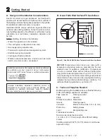
Appliance Dimensions Table
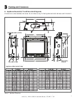
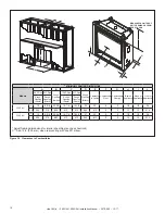
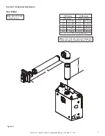
A. Appliance/Decorative Front Dimension Diagrams
Dimensions are actual appliance dimensions. Use for reference only. For framing dimensions and clearances refer to Section 5.
Figure 3.1 Appliance Dimensions
Q
R
Ø
O
P
L
M
N
GAS LINE ACCESS
T
S
C
V
A
B
U
E
D
F
ELECTRICAL
ACCESS
G
H
J
I
K
Ø
W
Ø
HEAT-ZONE®-240V ACCESS
XX
Y
350X-AU
550X-AU
Location Inches Millimeters
Inches
Millimeters
A
33
838
36
914
B
28-1/8
714
31-1/8
791
C
24-1/8
613
27-3/16
691
D
16
406
18-1/16
459
E
31-1/8
791
33-1/16
840
F
3-1/2
89
3-9/16
90
G
6-7/8
175
6-7/8
175
H
21-3/8
543
23-3/8
594
I
32-3/8
822
34-3/8
873
J
34-1/2
876
36-7/16
926
K
8
203
8
203
L
8-3/4
222
8-13/16
224
M
16-1/4
413
16-5/16
414
350X-AU
550X-AU
Location Inches Millimeters
Inches
Millimeters
N
1/2
13
1/2
13
O
22-3/4
578
25-3/4
654
P
11-3/8
289
12-7/8
327
Q
15-7/8
403
15-7/8
403
R
6-5/8
168
6-5/8
168
S
2-1/8
54
2-3/16
56
T
6
152
6
152
U
1
25
1
25
V
28
711
30-1/16
764
W
5
127
5
127
X
14
356
14
356
Y
9-1/8
232
9-1/8
232


