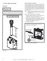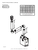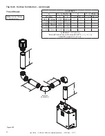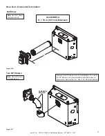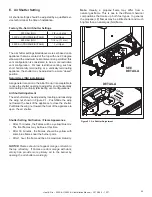
Heat & Glo • 350X-AU, 550X-AU Installation Manual • 2279-980
• 12/17
30
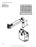
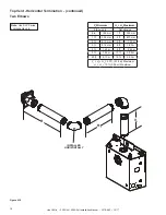
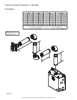
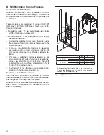
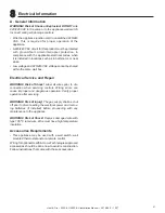
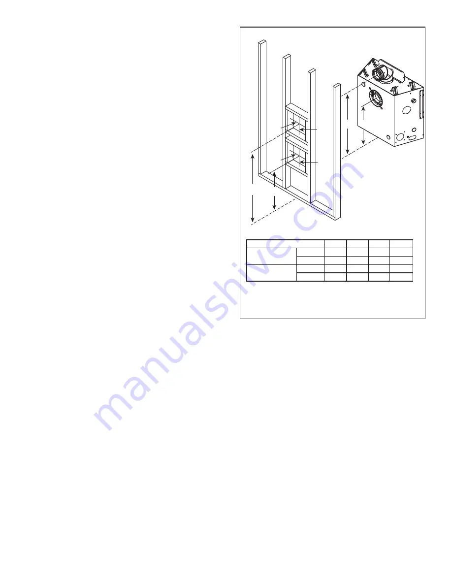
* Shows center of vent framing hole for top or rear venting.
The center of the hole is one (1) inch (25 mm) above the
center of the horizontal vent pipe.
C
D
A*
B*
10 in.
(254 mm)
10 in.
(254 mm)
10 in.
(254 mm)
10 in.
(305 mm)
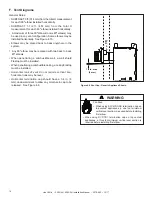
Figure 5.2 Wall Penetration
B. Wall Penetration Framing/Firestops
Combustible Wall Penetration
Whenever a combustible wall is penetrated, you must
frame a hole for the wall shield firestop(s). The wall shield
firestop maintains minimum clearances and prevents cold
air infiltration.
These clearances are maintained by using an SLP-WS
(SLP pipe) or DVP-WS (DVP pipe). See Figure 5.2 for
framing instructions.
• For external walls: The wall shield firestop is included
with the termination cap assembly.
• For internal walls: A wall shield firestop must be pur
-
chased and installed.
• The opening must be framed on all four sides using
the same size framing materials as those used in the
wall construction.
• SLP pipe - A wall shield firestop must be placed on
each side of an interior wall. A minimum 1-1/2 in. (38
mm) overlap of attached heat shields must be main-
tained.
• DVP pipe - A wall shield firestop is required on one
side only on interior walls. If your local inspector re-
quires a wall shield firestop on both sides, then both
wall shield firestops must have a heat shield (refer to
Section 12.A) attached to them.
• See Section 7.F for information for regarding the in-
stallation of a horizontal termination cap.
Non-Combustible Wall Penetration
If the hole being penetrated is surrounded by non-com-
bustible materials such as concrete, a hole with diameter
one inch greater than the pipe is acceptable.
Whenever a non-combustible wall is penetrated, the wall
shield firestop is only required on one side and no heat
shield is necessary.
A*
B*
C
D
350X-AU
Inches
35-1/2 22-3/8 34-1/2 21-3/8
Millimeters
902
568
876
543
550X-AU
Inches
37
24-3/8
36
23-3/8
Millimeters
940
619
914
594

