background image

Heat & Glo  •  SL-550TRSI-AUE  •  2079-902  Rev. B  •  7/06

36

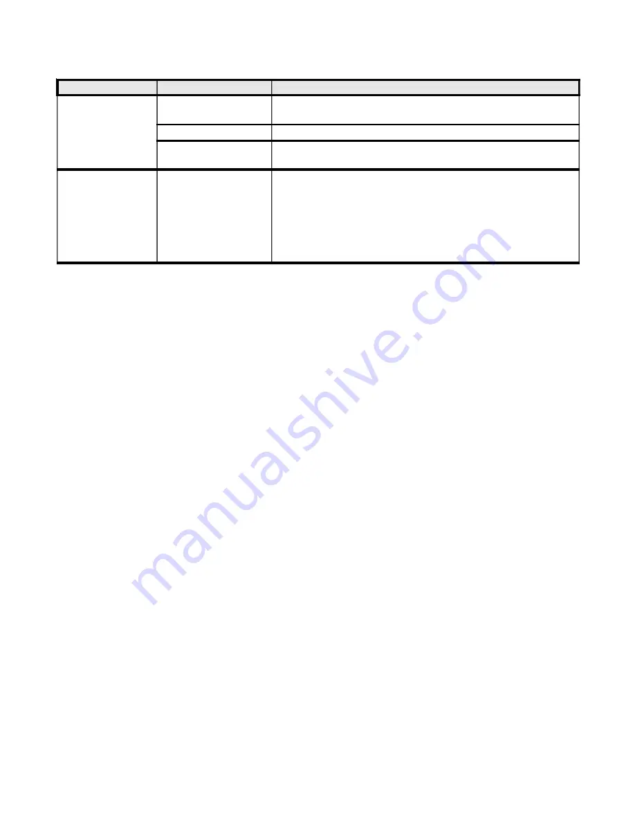
Electronic Ignition System - (continued)

Symptom

Possible Causes

Corrective Actions

10. Glass soots.

a.  Flame impingement on

logs.

Adjust the log set so that the flame does not impinge on it.

b. Improper venturi setting.

Adjust the air shutter at the base of the burner.

c. Debris around venturi.

Inspect the opening at the base of the burner. It is imperative that NO

material be placed in this opening.

11.  

Flame burns blue

and lifts off burner.

a.  Insufficient oxygen

being supplied.

1. Check to make sure flue cap is installed properly and free of debris.
Make sure that flue system points are tight and have no leaks.

2. Check to make sure that no material has been placed in the opening at

the burner base or in the area of the air holes in the center of the base

pan beneath the burne.

3. Be sure glass is tighened properly on unit, particularly on top corners.

Summary of Contents for SL-550TRSI-AUE

Page 1: ...NE OR MORE OF THE FOLLOWING PATENTS UnitedStates 4593510 4686807 4766876 4793322 4811534 5000162 5016609 5076254 5113843 5191877 5218953 5263471 5328356 5341794 5347983 5429495 5452708 5542407 5601073 5613487 5647340 5688568 5762062 5775408 5890485 5931661 5941237 5947112 5996575 6006743 6019099 6048195 6053165 6145502 6170481 6237588 6296474 6374822 6413079 6439226 6484712 6543698 6550687 6601579...

Page 2: ...he gas logs and flue system components are in separate packages Read all instructions before starting installation and follow these instructions carefully during installation to ensure maximum benefit and safety Fail ure to follow them will void your warranty and may present a fire hazard The Heat Glo a brand of Hearth Home Technologies Inc warranty will be voided by and Heat Glo a brand of Hearth...

Page 3: ...r Fan 24 1 6 Finishing 25 1 7 Installer Testing 26 1 8 Log Placement 27 2 0 Operating Instructions 30 2 1 Safety and Lighting Information 31 2 2 Fan Operation 32 3 0 Servicing and Maintenance 32 3 1 Removal of Covers for Servicing 33 3 2 Removal of Components for Service 33 3 3 Parts Replacement 33 3 4 Adjustments and Replacement Parts 33 3 5 Maintenance Tasks 34 3 6 Troubleshooting 35 4 0 Replace...

Page 4: ... in 203mm 36 3 8 in 924mm GAS LINE ACCESS 6 in 153mm 2 1 8 in 55mm 32 in 813mm 36 in 913mm 16 1 8 in 408mm 3 1 2 in 90mm 6 7 8 in 175mm 26 3 8 in 671mm 31 1 8 in 790mm Ø 6 1 2 in 165mm 32 5 8 in 828mm ELECTRICAL ACCESS 23 3 8 in 593mm TOP STANDOFFS FLUE COLLAR COVER PLATE HOOD DATA BADGE LABELS DRESS GUARD ACCESS DOOR GAS CONTROLS ELECTRICAL ACCESS GAS LINE ACCESS ...

Page 5: ...four 4 perimeter edges on the bottom of the unit Heater framing can be built before or after the heater is set in place Framing should be positioned to accom modate wall covering and heater facing material The heater framing should be constructed of 2 inch X 4 inch 51 x 102mm lumber or heavier The framing headers may rest on the heater standoffs Refer to Figure 2 and Figure 3 for heater and framin...

Page 6: ...e of the building WARNING THIS UNIT IS NOT FOR USE WITH SOLID FUEL These units MUST use the flue termination described in the flueing section of the manual The control system for this model is an electronic igni tion type It consists of a gas control valve variable regu lator a pilot sensor electrode and an ON OFF switch The controls are located behind the access door Ro tate the door down to open...

Page 7: ...ical air inlet P Electricity meter or fuse box areas for flue terminals a Below eaves balconies or other projections MIN CLEARANCE mm Appliances to 50 MJ h input 300 Appliances over 50 MJ h input 500 b From the ground or above a balcony 300 c From a return wall or external corner 500 d From a gas meter M 1000 e From an electricity meter or fuse box P 500 f From a drain or soil pipe 150 g Horizonta...

Page 8: ...ctly adhered to The rise to run relationships are shown in the flueing drawings and tables on the next few pages WARNING THIS GASAPPLIANCEAND FLUEAS SEMBLY MUST FLUE DIRECTLY TO THE OUTSIDE AND MUST NEVER BE ATTACHED TO A CHIMNEY SERVING A SEPARATE SOLID FUEL BURNING AP PLIANCE EACH GAS APPLIANCE MUST USE A SEPARATE FLUE SYSTEM COMMON FLUE SYS TEMS ARE PROHIBITED CAUTION UNDER NO CONDITION SHOULD ...

Page 9: ...H JOINT DVP90ST 319mm 286mm 184mm 32mm TYP 13mm TYP 217mm DVP36 DVP48 1219mm 610mm 914mm 102mm 152mm DVP4 DVP6 305mm DVP12 51mm MIN DVP12A 310mm MAX DVP24 251mm 45 0O 260mm DVP45 362mm Figure 6 DVP Series Balanced Flue Component Specifications 127mm inner pipe 203mm outer pipe ...

Page 10: ... pipe 6 5 8 inch 168mm outer pipe NOTE PIPES OVERLAP 1 3 8 INCHES 35mm AT EACH JOINT 6 5 8 168mm 9 5 8 244mm 6 3 8 162mm 6 3 8 162mm 6 165mm 9 5 8 244mm SL 90D 6 165mm 6 5 8 168mm 5 146mm 11 298mm SL 06D SL 12D SL 17 24D 17 24 432 610mm SL 09D SL 12 17D SL 24D SL 36D SL 48D 8 222mm 12 17 305 432mm 23 603mm 35 908mm 47 1213mm ...

Page 11: ...NLY Figure 10 USE DVP SERIES COMPONENTS ONLY STRAIGHTOUTHORIZONTAL FLUEING H Max Run 24 610mm Vertical Flue Restrictor If the heater installation requires a vertical flue ex ceeding 4 5m above the unit with no horizontal flue or elbows a vertical flue restrictor must be installed see Figure 8 Figure 8 H V CAP RESTRICTOR PLATE ...

Page 12: ...30 9 14M FLUEING WITH ONE 1 90 ELBOW USE SL D SERIES COMPONENTS ONLY Figure 12 USE DVP SERIES COMPONENTS ONLY FLUEING WITH ONE 1 90o ELBOW V FT H FT 1 MIN 0 30M 3 MAX 0 91M 2 MIN 0 61M 6 MAX 1 83M 3 MIN 0 91M 9 MAX 2 74M 4 MIN 1 22M 12 MAX 3 66M V H 36 MAX 10 97M H 12 MAX 3 66M H V V H NOTE A 146mm section of vertical pipe must be attached to the heater before a 900 elbow ...

Page 13: ...N 1 22M 8 MAX 2 44M 5 MIN 1 52M 12 MAX 3 66M 12 MAX 3 66M NOTE V V1 MAX 33 10 06M FLUEING WITH TWO 2 90 ELBOWS V H H1 FT M FT M 1 MIN 0 30M 2 MAX 0 61M 2 MIN 0 61M 4 MAX 1 22M 3 MIN 0 91M 6 MAX 1 83M 4 MIN 1 22M 8 MAX 2 44M 5 MIN 1 52M 10 MAX 3 05M 30 MAX 9 14M 10 MAX 3 05M FLUEING WITH TWO 2 90 ELBOWS USE SL D SERIES COMPONENTS ONLY H1 H V H V V1 ...

Page 14: ... 1 MAX 0 30M 2 MAX 0 61M 2 MIN 0 61M 2 MAX 0 61M 4 MAX 1 22M 3 MIN 0 91M 3 MAX 0 91M 8 MAX 2 44M 4 MIN 1 22M 4 MAX 1 22M 10 MAX 3 05M H 8 MAX 2 44M H H1 10 MAX 3 05M V H H1 30 9 14M MAX V FT H H1 FT 1 MIN 0 30 M 3 MAX 0 91M 2 MIN 0 61 M 5 MAX 1 52M 3 MIN 0 91 M 8 MAX 2 44M 4 MIN 1 22 M 12 MAX 3 66M H H1 12 MAX 3 66M V H H1 33 10 06m MAX H1 V H ...

Page 15: ...1M 6 MAX 1 83M 4 MIN 1 22M 4 MAX 1 22M 8 MAX 2 44M V V1 30 MAX 9 14M 6 MAX 1 83M 8 MAX 2 44M FLUEING WITH THREE 3 90 ELBOWS Figure 15 V H H1 FT M FT M 1 MIN 0 30M 2 MAX 0 61M 2 MIN 0 61M 4 MAX 1 22M 3 MIN 0 91M 6 MAX 1 83M 4 MIN 1 22M 8 MAX 2 44M 5 MIN 1 52M 12 MAX 3 66M 12 MAX 3 66M NOTE V V1 MAX 33 10 06M USE SL D SERIES COMPONENTS ONLY H1 H V1 V V1 H1 H V ...

Page 16: ... 6 MAX 1 83M 12 MAX 3 66M H 6 MAX 1 83M H H1 12 MAX 3 66M NOTE V V H H1 33 10 06M MAX V FT H FT H H1 FT V FT H FT H H1 H2 FT 1 MIN 0 30M 1 MAX 0 30M 2 MAX 0 61M 2 MIN 0 61M 2 MAX 0 61M 4 MAX 1 22M 3 MIN 0 91M 3 MAX 0 91M 8 MAX 2 44M 4 MIN 1 22M 4 MAX 1 22M 10 MAX 3 05M V H H1 H2 30 MAX 9 14M H 4 MAX 1 22M H H1 H2 10 MAX 3 05M FLUEING WITH THREE 3 90 ELBOWS USE DVP SERIES COMPONENTS ONLY V1 H V H1 ...

Page 17: ...gly Flueing Out the Rear Flue Remove the rear collar seal cap by cutting the strap at each end see Figure 17 Next remove the insulation from the rear flue pull the heat shield out from outside of the heater WARNING THE TOP FLUE COLLAR SEAL CAP MUST REMAIN ATTACHED TO THE TOP FLUE COLLAR IF THE FLUE SYSTEM IS ATTACHED TO THE REAR STARTING COLLARS SEE FIGURE 17 Flueing Out the Top Flue Remove the to...

Page 18: ...he heater At the same time slide the outer flue over the outer collar on the heater Push the flue section into the appliance col lar until all the lances see Figure 18 have snapped in place Tug slightly on the flue to confirm that it has completely locked into place Figure 18 Any 90 elbow installed directly on the back of a rear flueing heater MUST BE in a vertical position 2 Assembling Flue Compo...

Page 19: ...ether Slide the ceramic fiber pad over the first flue section and place it flush to the fireplace Continue to add vent components Figure 22 Adding Venting Components B On the TOP of the heater 1 Attaching the First Flue Component to the Start ing Collars To attach the first flue component to the starting collars on the top of the heater Lock the flue components into place by sliding the concentric...

Page 20: ... bottom of the firestop Continue the flue run through the firestop WALL BRACKET WALL STUD 8 FT 2 4m FLUE OUTLET 1 INCH MIN 25mm 10 254mm 12 305mm INTERIOR WALL SHIELD Figure 24 Flue Pipe Firestop For Vertical Runs One firestop is REQUIRED at the hole in each ceiling through which the flue passes To install firestops for vertical runs that pass through ceilings Position a plumb bob directly over th...

Page 21: ...ter Flue 38mm min Overlap Figure 27 Attic Firestop The termination kit should pass through the wall firestops from the exterior of the building Adjust the termination cap to its final exterior posi tion on the building and interlock the flue sections WARNING THE TERMINATION CAP MUST BE POSITIONED SO THAT THE ARROW IS POINTING UP Use a high temperature sealant gasket to seal be tween the pipe and e...

Page 22: ...of CAUTION FOLLOW THE REQUIREMENTS OF THE AGA GAS INSTALLATION CODE FOR MINIMUM HEIGHT REQUIREMENTS ABOVE THE ROOF To seal the roof hole and to divert rain and snow from the flue system Attach a flashing to the roof using nails and use a non hardening mastic around the edges of the flash ing base where it meets the roof Attach a storm collar over the flashing joint to form a water tight seal Place...

Page 23: ...ON SYSTEM WIRING This gas fireplace is equipped with an electronic igni tion system which operates on a 6 volt system This appliance requires 240 VAC to be wired to the factory installed junction box Check factory installed power cord for damage before using Shock Risk Replace damaged wire with type 105O C rated wire Wire must have high temperature insulation CAUTION Label all wires prior to disco...

Page 24: ...BLUE BLACK BROWN BLUE BROWN BLUE BLACK GREEN YELLOW STRIPE GREEN YELLOW STRIPE 1 5 BLOWER FAN These heaters have a factory installed Fan Elec trical Junction Box Variable Speed Rheostat Control Switch and Temperature Sensor Switch for the fan These components are located be hind the lower door Use of the fan requires that the Junction Box factory installed be connected to 240 VAC service before pe...

Page 25: ...UND TOP AND SIDES ARE SEALED A 300 F 149 C MINIMUM SEAL ANT MATERIAL MUST BE USED THESE JOINTS ARE NOT REQUIRED TO BE SEALED ONLY NON COMBUSTIBLE MATERIAL USING 300 F 149 C MINIMUM ADHESIVE IF NEEDED CAN BE AP PLIED AS FACING TO THE FIREPLACE SUR ROUND SEE FIGURE 33 TOP SEAL JOINT SIDE SEAL JOINT 1 2 13mm 0 FINISH MATERIAL MAY BE COMBUSTIBLE TOP AND SIDES OF UNIT CEILING 31 787mm 12 305mm 11 279mm...

Page 26: ...rding to manufacturer s specifications prior to the in staller leaving the site Note the tips of the flames should never hit the top of the firebox after the unit has warmed up Please contact your dealer or a qualified service person to replace injector or adjust valve Upon completing the gas line connection a small amount of air will be in the lines When first lighting the pilot light it will tak...

Page 27: ... that the notches in the bottom of the log fit on the right three grate bars Push log 1 towards the rear locating tabs LOG 2 SRV347 703 Place log 2 so that its left edge sits against the left front grate corner and its right edge rests against the tab on the second grate bar 1 8 LOG PLACEMENT INSTRUCTIONS Log Set Assembly LOGS 550TRSI AUE 1 1 2 2 TABS 1 2 3 4 5 6 7 8 ...

Page 28: ... Push its left hand side back to the locating tab as the grate bar LOG 5 SRV540 704 Put the forked end of log 5 on the base in front of the grate towards the center of the second bar grate 4 4 5 5 LOG 3 SRV349 704 Position log 3 so that its right edge sits on log 1 as shown and it s left edge sits on the first grate bar behind log 2 3 3 ...

Page 29: ... log 7 on the groove in log 2 with its rear top on log 1 and front top resting on log 5 LOG 8 SRV347 701 Hook log 8 on the right hand corner grate bar and rest its rear on log 1 as shown 7 7 8 8 LOG 6 SRV550 718 Place log 6 on the base on front of the grate as shown 6 6 ...

Page 30: ...not affect the operation or lon gevity of the heater OPERATING CAUTIONS THIS APPLIANCE MAY EXHIBIT A SLIGHT CARBON DEPOSITION DO NOT PLACE ARTICLESONOR AGAINST THIS APPLIANCE DO NOT USE OR STORE FLAM MABLE MATERI ALS NEAR THIS APPLIANCE DO NOT SPRAY AEROSOLS IN THE VICINITY OF THIS APPLIANCE WHILE IT IS IN OPERATION THE DRESS GUARD IS FITTED TO THIS APPLI ANCETOREDUCETHERISKOFFIREORINJURY FROM BUR...

Page 31: ... manual provided with this ap pliance This appliance needs fresh air for safe operation and must be in stalled so there are provisions for adequate combustion and ventila tion air If not installed operated and main tained in accordance with the manufacturer s instructions this product could expose you to sub stances in fuel or fuel combustion Keep burner and control compart ment clean See installa...

Page 32: ...at least twice a year CAUTION THE LOGS GET VERY HOT HANDLE ONLY WHEN COOL WARNING DO NOT USE ABRASIVE CLEANERS ON THE GLASS DOOR AS SEMBLY DO NOT ATTEMPT TO CLEAN THE GLASS DOOR WHEN IT IS HOT F The glass door should be cleaned using a house hold glass cleaner DO NOT handle or attempt to clean the glass when it is HOT G Visually inspect the flexible power supply cord if damaged contact the service...

Page 33: ...remove the pilot assembly from the bracket NOTE When removing the pilot assembly carefully pull the electrode wire up through the grommeted hole in the base pan 3 3 PARTS REPLACEMENT 1 FAN SWITCHES Disconnect the fan wires from the junction box wires by pulling the male and female connectors apart and slide the fan out the front of the lower controls com partment Disconnect the wires from the fan ...

Page 34: ...ct for paint condition warpage corrosion or perforation Sand and repaint as necessary 2 Replace gas fireplace if firebox has been perforated Burner Ignition and Operation 1 Verify burner is properly secured and aligned with pilot or igniter 2 Clean off burner top inspect for plugged ports corrosion or deterioration Replace burner if necessary 3 Replace ember materials with new dime size and shape ...

Page 35: ... in location along cable d Valve Replace valve Do not over tighten e Over tightened thermocouple interrupter Replace valve and thermocouple interrupter f Receiver Replace receiver and reprogram code 5 Pilot is lit and control continues to spark Valve shuts off after 10 to30 seconds Valve operates manually a Receiver Replace receiver and reprogram code 6 Pilot is lit sparking stops if a flame is pr...

Page 36: ...pening at the base of the burner It is imperative that NO material be placed in this opening 11 Flame burns blue and lifts off burner a Insufficient oxygen being supplied 1 Check to make sure flue cap is installed properly and free of debris Make sure that flue system points are tight and have no leaks 2 Check to make sure that no material has been placed in the opening at the burner base or in th...

Page 37: ... LP Exploded Parts Diagram Service Parts SL 550TRSI AUE Beginning Manufacturing Date 6 06 Ending Manufacturing Date ______ 22 Log set assembly 19 6 23 25 27 24 26 28 30 29 10 16 17 2 1 3 18 15 14 13 12 7 8 11 9 21 4 33 37 32 31 20 34 36 5 35 38 39 40 ...

Page 38: ...sembly LP 2098 051 17 Switch Assembly 2098 145 18 Interior Top Heat Shield 2079 109 19 Gas Shutoff Assembly 2078 022 20 Rheostat 491 510A 21 Switch Sensor 046 530 22 Log Set Assembly LOGS 550TRSAUD 23 Log 1 SRV550 715 24 Log 2 SRV347 703 25 Log 3 SRV349 704 26 Log 4 SRV278 705 27 Log 5 SRV540 704 28 Log 6 SRV550 718 29 Log 7 SRV484 703 30 Log 8 SRV347 701 31 Valve Plate Gasket 530 431 32 Pilot Bra...

Page 39: ...replacement parts at the current wholesale price defective electrical or manual components optional components or accessories and glass panels not including glass panels broken during misuse or careless handling HEAT GLO shall not be responsible for any labor transportation or other costs Furthermore it shall not be liable for any indirect incidental or consequential damages 3 HEAT GLO will replac...

Page 40: ...7 06 40 For Service or Replacement Parts Contact Melbourne Jetmaster 444 Swan Street Richmond 3121 03 9429 5573 Perth Fireplace Corner 277 Lord Street East Perth 6000 08 9228 2600 Sydney Jetmaster 10 Martin Avenue Arncliff 2205 02 9597 7222 ...

Reviews: