Heat & Glo • SL-36-Ultimate • 2141-900 Rev. i • 5/11
32
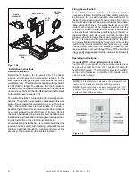
Figure 10.3.
Installation instructions
Determine location
Determine the location for the wall switch. The chosen
location should provide an accessible location in the
same space as the gas fi replace. Never place this unit in
a separate room. The control wire supplied with this switch
is 33 ft (10M) in length. The distance from the fi replace to
the switch may be lengthened provided that the wire used
never exceeds 50 ft, and that the distance from the fi replace
to the switch never exceeds 30 ft.
The switch should be mounted into a listed electrical junc-
tion box. The junction box should be dedicated to this wall
switch. Never install this wall switch into a junction box
that is shared with other electrical service or devices. If
possible, install this unit on an interior wall of the residence
at a recommended height of 5 ft from the fl ooring. Should
the switch be installed on an exterior wall, be certain wall
insulation is kept intact and not damaged or dislodged dur-
ing the installation of the electrical junction box.
For exterior wall installations, it is recommended that the
junction box be sealed with caulking material. This will
minimize heat loss through this location and improve the
accuracy of the automatic (thermostat) operation.
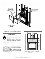
CONTROL
BOX
CONTROL
WIRE
WALL SWITCH
COVER
PLATE
FLAME
SOLENOID
Wiring the wall switch
Once a location is chosen and the electrical box is installed
proceed as follows. Install the provided control wire from
the fi replace to the switch location. Use caution not to
stress the wire around tight or sharp corners. Do not run
the control wire adjacent to existing or future phone, data,
cable, or electrical lines. The wire should not come into
contact with any part of the fi replace exterior with the
exception of where it exits the outer wrap. Feed the wire
to the electrical junction box and through a provided or
approved strain relief. Using a screw driver, connect the
red wire to the “R” terminal, the yellow or white wire to the
“W” or “Y” terminal, and the green wire to the “G” terminal.
Do not over-tighten. Using the screws provided, mount the
switch to the electrical junction box right side up. Install
provided cover plate using the screws provided. Do not
use a substitute cover even though it may fi t. The provided
one is specifi cally designed for the automatic (thermostat)
function of the unit.
Operating Instructions
For units WITH factory installed rocker switch.
The ON/OFF rocker switch on the fi replace (located near
the gas valve) must be in the “OFF” position for use with
the WSK-MLT system. The ON/OFF rocker switch will NOT
function with this device on Intellifi re (IPI) models except
during a power outage.
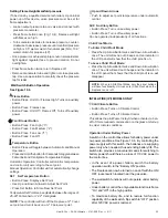
Figure 10.4
NOTE:
The temperature displayed by the wall switch may
take up to 30 minutes to stabilize on initial power-up.
NOTE:
Check control box and assure switch is in the “OFF”
position. This switch is only used on Intellifi re (IPI) control
systems under battery operation.

