Heat & Glo • SL-750TRS-IPI-D, SL-550TRS-IPI-D, SL-350TRS-C • InD • 2065-985 Rev. o • 3/07
32
For Vertical Runs -
The vent system must be supported
every eight (8) feet (2.4m) above the appliance
À
ue outlet by
wall brackets. To install support brackets for vertical runs:
• Attach wall brackets to the vent pipe and secure the wall
bracket to the framing members with nails or screws.
Continue Adding Vent Components
• Continue adding vent components, locking each suc-
ceeding component into place.
• Ensure that each succeeding vent component is securely
¿
tted and locked into the preceding component.
• 90° elbows may be installed and rotated to any point
around the preceding component’s vertical axis. If an
elbow does not end up in a locked position with the
preceding component, attach with a minimum of two (2)
sheet metal screws.
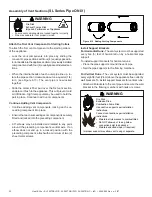
Figure 8.12 Adding Venting Components
Install Support Brackets
For Horizontal Runs -
The vent system must be supported
every
¿
ve (5) feet of horizontal run by a horizontal pipe
support.
To install support brackets for horizontal runs:
• Place the pipe supports around the vent pipe.
• Nail the pipe supports to the framing members.
Attach the First Vent Component to Starting Collars
To attach the
¿
rst vent component to the starting collars
of the appliance:
• Lock the vent components into place by sliding the
concentric pipe sections with four (4) equally spaced in-
terior beads into the appliance collar or previously installed
component end with four (4) equally spaced indented sec-
tions.
• When the internal beads of each outer pipe line up, ro-
tate the pipe section clockwise about one-quarter (1/4)
turn (see Figure 8.13). The vent pipe is now locked
together.
• Slide the ceramic
¿
ber pad over the
¿
rst vent section
and place it
À
ush to the appliance. This will prevent cold
air in
¿
ltration. High temp caulk may be used to hold the
part in place. Continue to add vent components.
Fire Risk
Exhaust Fumes Risk
Impaired Performance of Appliance
WARNING
• Ensure vent components are locked together correctly.
• Pipe may separate if not properly joined.
Fire Risk.
Explosion Risk.
Combustion Fume Risk.
Use vent run supports per installation
instructions.
Connect vent sections per installation
instructions.
• Maintain all clearances to combustibles.
• Do NOT allow vent to sag below
connection point to appliance.
• Maintain
speci
¿
ed slope (if required).
WARNING
Improper support may allow vent to sag or separate.
Assembly of Vent Sections
(SL Series Pipe ONLY)


