background image

Section 5-3

18

MLSM2003-01-03

Procedure 2 

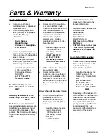
- Terminal Block

Step 1:  Disconnect power supply
to range. Pull range away from wall.

Step 2:  Remove back panel. Refer
to Procedure 32 for details.

Step 3:  Inspect terminal block for
burnt terminal connections.  If
damaged, replace.

Step 4:  To replace terminal block,
remove power cord by unscrewing
the three screws that retain the
ends of the cord to the terminal
block.

Step 5:  Mark and disconnect all
wires attached to the terminal block
(including wire to ground stud for 4
prong power cords)

Step 6:  Terminal block can be
removed from range by removing
the two center screws.

Step 7:  Install new terminal block,
attach all red, white and black wires
as originally marked

Step 8:  Attach power cord back on
terminal block. Be sure all wires are
secure.  3 prong power cords have
jumper cable from center (neutral)
side of terminal block to stud. 4
prong power cords have copper
wire from cord directly attached to
ground stud.

Summary of Contents for 3520

Page 1: ...CE MANUAL for HEARTLAND APPLIANCES Metro Legacy Lines Model 3520 30 Legacy Model 3525 30 Metro Model 3620 36 Legacy Model 3625 36 Metro Diagnosis Charts Service Procedures Component Data Heartland Appliances Inc Manual No MLSM010601 ...

Page 2: ...eart land assumes no liability for any errors omissions or any defects whatsoever in the diagrams and or repair proce dures or for any damage or injury resulting from utiliza tion of said diagrams and or repair procedures Safety Information Electric and Gas Ranges are complex electromechanical devices Any attempt to repair a range may if improperly performed result in personal injury or property d...

Page 3: ...ction 2 Parts Warranty Information 7 Section 3 Technical Specifications 9 Section 4 Problem Diagnosis Charts 11 16 Section 5 Repair Procedures 17 56 Section 6 Wiring Diagrams Models 3520 3525 57 Models 3620 3625 58 Section 7 Exploded Views and Parts List 59 60 ...

Page 4: ...4 MLSM2003 01 03 PAGE LEFT BLANK ...

Page 5: ...g any such check ensure no other conductive parts panels or yourself come into contact with any exposed current carrying parts 3 If a replacement part is required ensure it meets factory specifications 4 Never by pass or interfere with the proper operation of any feature part or device engineered into the product 5 Prior to reconnecting electrical power service to the product ensure that a all ele...

Page 6: ...6 MLSM2003 01 03 PAGE LEFT BLANK ...

Page 7: ...es Inc 1050 Fountain St N Cambridge Ontario N3H 4R7 ph 877 650 5775 fx 800 327 5609 Service Department Extensions 2241 2264 2244 CSF number to be referenced in all warranty claims Contacting Heartland Appliances prior to performing service work will assist in the diagnosis of the problem this should result in having to go to the customer s home only once How To Submit Warranty Claims For prompt wa...

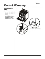
Page 8: ...ty Serial Number Location in Ranges Metro Legacy ranges have the serial number located at the back of the range and on the kick plate To view serial number plate open door and look at kickplate s right top corner view shown with door removed ...

Page 9: ...atural Gas 6 w c Propane 11 w c NPT 5 8 flex line Surface Burners 4 15 500 Btu Grill Burners 2 7 500 Btu Note Service Amperage to be calculated by a qualified electrician Electrical Requirements Standard 240V 60 Hz receptacle properly polarized on its own dedicated line must be used Ranges are provided with a molded plug cap power cord rated at 120 240 Volts Ranges must be electrically grounded in...

Page 10: ...Section 3 10 MLSM2003 01 03 PAGE LEFT BLANK ...

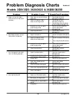
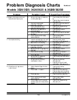
Page 11: ...relay board Procedure 18 ü Check 25 amp relay Procedure 21 Breaker tripped or fuse blown Timer blank no power to timer Timer not set to time of day Timer cannot be programmed Timer programmed to delayed time bake Open wire or poor connection at oven thermostat probe F1 displayed in timer Open bake broil limit relay Timer programmed to self clean timer displays SC Tripped or open safety limit red b...

Page 12: ...ke broil limit ü Check broil element Procedure 11 ü Check broil element Procedure 11 ü Check relay board Procedure 18 ü Check timer Procedure 4 ü Check coaxial cable Procedure 18 ü Check bake broil limit Procedure 7 7 Oven temperature incorrect oven not baking properly Open thermostat probe Faulty bake broil limit cycling on off at lower temperatures Faulty Timer Open timer coaxial power supply ca...

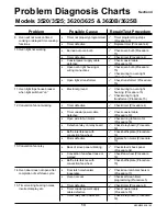
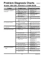
Page 13: ...nvection fan not working Timer defective Timer coaxial power cable defective Open wire to fan motor Defective relay on relay board Baffle interference with convection fan wheel Motor defective ü Check timer Procedure 4 ü Check coaxial cable Procedure 19 ü Check wiring to fan motor Procedure 16 ü Check relay board Procedure 18 ü Check baffle plate Procedure 16 ü Replace fan motor Procedure 16 13 Co...

Page 14: ... not heating Door latch mechanism inoperative or stuck Bake broil limit not bypassed or defective Oven door not sealing Timer defective Safety limit not calibrated properly or defective No signal from self clean mechanism to timer House breaker tripped or fuse blown Timer blank no power Timer defective Timer coaxial power supply cable defective Timer locked out 3 horizontal red lines present in te...

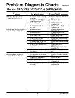
Page 15: ...n Procedure 20 ü Check cooling fan Procedure 20 21 Cooling Fan stays in on position for several hours Faulty fan limit Self Clean Latch not fully retracted ü Check cooling fan Proc 20 ü Check door latch mechanism Procedure 17 22 Top burner does not ignite No gas to burner Faulty ignition switch Open wire to ignition switch Burner valve stem cannot be turned Open wire from ignition switch to spark ...

Page 16: ...iring Procedure 3 ü Check burner valve Procedure 29 ü Check power supply Procedure 1 ü Check wiring and connections Procedure 1 ü Check air shutters Procedure 26 25 Electrodes spark when ignition switches are in off position Ignition switch faulty Ignition switch wet Spark module faulty Loose ground in range or defective power cord Valve stem not level keeping switch from turning off Loose ground ...

Page 17: ...cartridge type fuses joined together at the handle Step 5 Pull block out of panel Step 6 Fuses can be checked with ohnmmeter set at the lowest resistance scale Touch probes to brass caps at each end If no continuity then replace with fuse that meets local electrical codes and is not larger than specified for the range Step 7 Clip fuses firmly back on panel ON notation should appear at the top of t...

Page 18: ...he cord to the terminal block Step 5 Mark and disconnect all wires attached to the terminal block including wire to ground stud for 4 prong power cords Step 6 Terminal block can be removed from range by removing the two center screws Step 7 Install new terminal block attach all red white and black wires as originally marked Step 8 Attach power cord back on terminal block Be sure all wires are secu...

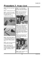
Page 19: ...and strain relief clamp for signs of damage If damaged replace See Procedure 2 for details Step 7 If no visible damage detected check individual wires in the power cord with a multimeter Step 8 Place one test probe on the wire end and the other test probe on the plug end If no continuity replace power cord Step 9 For 3 prong cords outer terminal wire end black side should indicate continuity to on...

Page 20: ...locking tabs Step 6 Disconnect two molex plugs from clock Double black wire molex plug is positioned on the connector closest to the bottom of the timer Molex plug with white black wires is positioned on the connector closest to the top of the clock Note Black white wire molex plug is the oven thermostat probe wiring Double black molex plug is the self clean microswitch wiring Step 7 To replace ti...

Page 21: ...up button temperature time count down button Step 5 To set cooking press desired function bake convection bake or broil Note automatically sets to 325F for bake and convection bake and to 550F for broil Step 6 Press increase or decrease symbols to select time Step 7 Press start symbol to start Note To toggle between Fahrenheit F and Celcius C press cooking symbol twice in a row Self Clean Programm...

Page 22: ...y removing locking nuts please note that there is a left and right rack support with the v always facing downward Step 7 Remove baffle s two bottom screws first you may use a prop for the baffle such as 2 wide masking tape roll Step 8 Remove top two screws and gently pull baffle plate out clearing oven probe s opening Step 9 Place tape overtop probe s screw heads inside oven Step 10 Disconnect mol...

Page 23: ...ents to limit and from relay board to limit for signs of damage and continuity Also check wires to safety limit Procedure 8 and to self clean microswitch selector Procedure 17 Step 9 To replace bake broil limit open oven door and remove for easier access See Procedure 33 Step 10 Place masking tape over nut head protruding inside the oven to hold in place Step 11 From back of range remove nut s hol...

Page 24: ...ton had tripped safety may be out of calibration Calibrate or replace Step 8 To access safety limit remove nut holding safety limit from underneath bottom using 7 16 nut driver Step 9 Remove one out of two screws from top clip and slide out of way With thin blade screwdriver adjust calibration Turn 45 deg CCW to increase temperature limit 125F or CW to decrease by 125F Step 10 If replacing safety ...

Page 25: ...element removed test for continuity Place test probes on each terminal Needle should read approximately 25 ohms for 3500W elements and 16 ohms for 5 000W elements If no reading or significantly different replace Step 7 Test bake element for grounding as well by setting multimeter to Rx1 resistance Place one test probe on one terminal and other on metal sheath If reading changes the element is grou...

Page 26: ...ntinuity Place test probes on each terminal Needle should readapproximately 24 ohms for 2400W elements For 36 models test two inner leads and two outer leads for continuity If no reading or significantly different from range replace Step 8 Test bake element for grounding as well by setting multimeter to Rx1 resistance Place one test probe on one terminal and other on metal sheath If reading change...

Page 27: ...hould read approximately 24 ohms for 3500W elements 36 models use two 2500W broil plates and each plate has four leads Test the two outer and the two inner leads for approximately 45 ohms If no reading or significantly different from range replace Step 5 If element faulty Replace Remove stove top Procedure 26 and burner overflow trays Step 6 Remove sheet metal cover and insulation over top broil e...

Page 28: ... and outer loop Step 3 Insert new gasket starting from one bottom corner and loosely tighten first screw Step 4 Work your way around the perimeter tightening the corner screws as the gasket is being fed Step 5 Ensure gasket is even throughout and tighten all screws Note When placing door back onto stove insert hinges into receivers and open door fully Disengage brass catches prior to closing door ...

Page 29: ...in Step 3 Drill out 9 64 diameter rivets and pull defective hinge away from door frame Step 4 Insert new hinge assembly and using hand held rivet rivet new hingein place Step 5 Place door back in stove Insert hinges into receivers and open door fully Disengage brass catches prior to closing door Failure to do so will damage the hinges See Procedure 33 for full details ...

Page 30: ...his component Step 3 Inspect opening to vent for signs of excessive foreign substances Step 4 Pull unit away from the wall Step 5 Remove top cresting splashback and inspect the vent ensure vents have appropriate clearance If blocked or not level replace Step 6 To replace oven vent remove screws holding oven vent to oven cavity from inside oven Step 7 Remove stove s back panel Procedure 32 Step 8 T...

Page 31: ...lcohol first Step 7 If bulb tests in good order however oven light does not operate check light housing Step 8 Pull unit away from wall and remove range s back panel see Procedure 32 Step 9 Inspect for signs of damage at light transformer Test transformer for continuity across terminals If faulty replace Step 10 Disconnect wires from old transformer and place in new one Step 11 If Transformer is i...

Page 32: ...from inside oven see Procedure 6 steps 5 8 Step 7 Remove convection fan wheel by turning center locking nut CW not CCW It is easier to hold nut firmly and turn fan wheel clockwise Ensure retainer clip is transferred to new fan Step 8 From back of stove remove three mounting screws and transfer wires to new motor Step 9 Sometimes convection fan wheel may become loose or warped and rattle against th...

Page 33: ... unit will not self clean properly since cooling fan will not engage during self clean and safety temperature limit in timer will shut down operation Step 8 Test microswitch for continuity when button is depressed across terminals 1 and 2 by placing test probes on terminals If no continuity in the on position replace switch Step 9 To replacem unscrew microswitch from support place and transfer red...

Page 34: ...n place and replace with new latch Step 13 Do not over tighten screws as they must allow movement of the latch back and forth Procedure 17 Self Clean Latch Mechanism Self Clean Operation Clock programmed to self clean door automatically locks wax motor is energized and pushes latch to lock and cooling fan starts Regular bake broil limit is bypassed and temperatures cycle off the timer When door lo...

Page 35: ... panel see Procedure 32 Panel is held in by a series of self tapping screws Step 3 Carefully pull away from range and drop relay cover to access relay board Step 4 Remove one wire at a time from faulty relay board unto new board Step 5 Remove four nuts holding relay board to access panel ensure that non conductive spacers are also transferred to new board ...

Page 36: ...ess timer coaxial power supply cable Step 4 Inspect cable for visible damage and replace as needed If timer does not operate properly one of probable components is the coaxial cable other probable components are the timer and the relay board Step 5 Pull locking tabs away and release cable from relay board Step 6 Release coaxial cable from timer see Procedure 4 for timer access Step 7 Replace cable...

Page 37: ...fan limit Step 5 To access fan limit remove control panel see Procedure 34 Step 6 If fan and wiring in good condition test fan limit for continuity Remove both red wires and test across limit should be open and no reading taken across terminals Step 7 If limit test in good condition inspect self clean assembly microswitch see Procedure 17 Step 8 If limit is faulty replace remove wires to limit and...

Page 38: ...y cover to access 25 amp Relay Step 4 If range s oven is not operational pull wires from relay and test continuity across each side If relay faulty replace Sometimes relays malfunction only under load carefully plug range ensure no wires are making contact with any metal parts and test for voltage across the relay Step 5 If relay is faulty replace and transfer wires to new relay in the same sequen...

Page 39: ...ntrols left two burners Step 4 There should be no continuity across any of the corresponding terminals from one side of the module to the other If any show continuity replace spark module Step 5 To replace faulty spark module remove one wire at a time from old module and transfer to new module in the exact same terminals as the original Please ensure quick connect leads are properly and fully inse...

Page 40: ...ible damage and replace if necessary Switch can be tested by testing continuity across terminals in the on position Pull wires and place probes at each terminal and test Procedure 23 Ignition Switches Step 5 To replace switch disconnect wire connections from faulty ignition switch and transfer to new switch Step 6 Remove one mounting screw with phillips screwdriver to disconnect switch from burner...

Page 41: ...er appliances on the same line or too small piping i e 3 8 will lead to performance problems small flames etc due to low pressure Step 3 Pressure to regulator regulator included with range can be checked by inserting a tester into access port It should read 4 w c If regulator is defective then replace see Procedure 210 Step 4 Sometimes the stove may have the incorrect gas setting for the gas being...

Page 42: ... there is gas to the regulator it is either mounted backwards very unlikely however there is an arrow stamped on the body of the regulator to ensure proper orientation or it is faulty Step 6 If installed backwards disconnect regulator from manifold and inlet piping reverse orientation and re install Check all gas connections with soapy water solution to ensure no gas leaks Step 7 If regulator is f...

Page 43: ...s Step 8 To reverse regulator cap remove with large flat blade screwdriver turning CCW The gas being converted to must be stamped on the outside of the cap Position cap back on regulator press and turn CW to lock in place Step 9 Burner valves simmer jet conversion Use small flat blade screwdriver to remove original simmer jets and replace with appropriately numbered simmer jets all jets have their...

Page 44: ...d adjusting LP fully open Nat Gas open 0 40 North American Natural Gas Description Size Part no Model 3520 3525 3620 3625 3620 3625 BBQ 38109 38110 38111 main jet simmer 34 3669 4 6 4 main jet 1 7 3860 4 6 4 valveouter 0 4 7640 OR 3856 4 6 4 valveinner 0 88 3857 4 6 4 grill Jet 1 18 3516 0 0 2 grill valve 0 58 7636 0 0 2 venturi 3667 4 6 4 North American Liquid Propane Description Size Part no Mod...

Page 45: ...tep 2 Caps must lock in place to ensure a flat surface is provided and flames are evenly distributed out of cap ports Burner ring not locked results in uneven flames Ports Important tab must be locked in position on the burner base Step 3 Other causes for erratic sparking are moisture inside caps specially after washing or food particles blocking the ports correct incorrect ...

Page 46: ...rode to base with needle nose pliers by sliding off horizontally from underneath the top Step 10 Pull wire from faulty electrode and transfer to new electrode Step 11 Place electrode onn burner base by squeezing C clamp between electrode and burner bowl slot Step 12 If electrode and wire test in good condition check wiring and connections at spark module see Procedure 22 or at ignition switch see ...

Page 47: ...23 Wires can remain on switch if new valve does not have switch factory installed Step 5 Disconnect burner valve from manifold by removing two 8 mm nuts Step 6 Install new burner valve to manifold ensure new valve has the o ring gasket to seal against the manifold If not transfer seal from old valve Step 7 Attach aluminum tube to new valve Step 8 Turn gas on and test for gas leaks with soapy water...

Page 48: ...modules see Procedure 32 Look for loose or damaged wiring and connections at spark module Procedure 22 or at terminal block Procedure 2 Step 4 Ensure burner valve stems are level If stem is out of alignment it could maintain the ignition switch in the on position although no gas flows to the burner See Procedure 29 for burner valve replacement Step 5 A faulty igntion switch can also cause random s...

Page 49: ...tep 7 Once screws are removed pull blower to the left to free tabs and out Step 8 Blowers are held in place by two screws fastening the blower to the top of the hood and by small tabs Step 9 Once screws are removed pull blower to the left to free tabs and out Hood Removal disconnect power to hood Step 10 Disconnect wires to terminal block hoods are all hard wired as they are not supplied with a wa...

Page 50: ...essing on bottom metal clips to loosen Step 15 Remove screws holding main splashback to wall near the bottom Step 16 Remove two upper screws holding splashback to wood mounting strip Step 17 If needed remove 7 extension panel Step 18 If needed remove wood mounting strip Procedure 31 Closet Exhaust Fan 7 H igh top extension C L Hood ...

Page 51: ... outer row of screws securing the back panel to range start with bottom screws and work towards the screws near the top Step 4 When removing last screw hold on to panel to prevent dropping Step 5 Gently pull panel back and disconnect red and black wires to cooling fan do not forget to re attach these at the end of any service work Relay Board Panel Removal Step 6 Relay board can be accessed by rem...

Page 52: ...nge Step 11 Pull unit away from wall Step 12 Prop top up see Procedure 35 Step 13 Remove three screws from the side panel near the bottom Step 14 To access components swing side panel outwards Step 15 To replace panel remove one screw holding panel to range front Step 16 Pull side panel up and away from stove Transfer screw from old panel to new panel and attach to stove front through keyhole slot...

Page 53: ...oor lift door up and at a 30 degree angle in one sweeping motion Note Door weighs approximately 40 lbs 18 kgs Exercise caution when removing Place door with handle facing down on protected surface Step 4 Whan placing door back onto range insert hinges into receivers as far in as possible Step 5 open door fully and disengage brass catches completely With brass catches out of the way close door slow...

Page 54: ...ratch the surface Step 5 Use 3 8 extended socket nut driver to loosen nuts holding control panel to top The control panel is fastened with 2 or 4 nuts for 30 and 36 models respectively to studs welded to the stove top Use of a flashlight will help in seeing the nuts first and then it will be easier to feel the nuts with the driver Step 6 Once nuts are loose pull control panel away from stove Step ...

Page 55: ...Step 3 Pull stove top upwards by holding the front of the stove top and the back and pulling upwards A gentle tap may be needed to dislodge the pems holding the top to the stove s side panels Step 4 Note that the flexible gas line may get stuck on the stove s back opening and impede the pulling of the stove top gently feed the gas line through the hole Step 5 Use padded spacers or two short 2x4 pi...

Page 56: ...ds as straight as possible to free from stove Step 5 Replace with new burner bowl please reinsert as vertical as possible Step 6 Reattach burners to new burner bowl by pulling center of burner base upwards and lining up screw holes Step 7 Legacy Models Remove three slot screws per each burner base and allow the burner base to gently drop into the stove s cavity Step 8 Prop stove top Procedure 35 a...

Page 57: ...Section 6 57 MLSM2003 01 03 Wiring Diagrams Models 3520 3525 ...

Page 58: ...Section 6 58 MLSM2003 01 03 Wiring Diagrams Models 3620 3625 ...

Page 59: ...03 01 03 Exploded View Parts Models 3520 3525 3620 3625 3620B 3625B 3576I 3653 3364 6455 3457 3350 3660 3662 3669 3663 3661 36801 36802 3665 3552 30 3650 30 3655 36 3551 36 3656 30 3658 36 Front Burners Rear Burners 3565CB ...

Page 60: ...rner base Venturi Air Shutter included European only 3665 Dual burner base Venturi Air Shutter included N A only 3669 Dual burner beauty trim ring Black 3663 Dual burner cross ring Brass 3661 Dual burner inner base Brass 3660 Dual burner inner head Black 3662 Dual burner outer head Black 3689 Dual burner valve LP C Colour to be specified Part Description 3688 Dual burner valve N G 36802 Electrode ...

Reviews: