Section 5-3
43
MLSM2003-01-03
Procedure 26
- Gas Conversion
Please contact factory for
conversion kit appropriate for
the range. Serial number of
range must be provided to
ensure correct kit is ordered.
Conversion Steps:
Step 1: Disconnect gas supply and
electric power supply.
Step 2: Remove range’s back
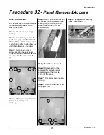
panel (see Procedure 32).
Step 3: Remove control panel (see
Procedure 34)
Step 4: Disconect wiring to timer
(Procedure 4)
Step 5: Mark and disconnect
wiring to fan limit (Procedure 20)
Step 6: Mark and disconnect
ground (green), neutral (white) and
power (black) wires to spark
module.
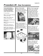
Step 7: Pressure regulator
conversion. Regulator has
reversible cap for either Natural
Gas or Propane. See Procedure 25
for details on regulator access.
Step 8: To reverse regulator cap,
remove with large flat blade
screwdriver turning CCW. The gas
being converted to must be
stamped on the outside of the cap.
Position cap back on regulator,
press and turn CW to lock in place
Step 9: Burner valves simmer jet
conversion. Use small flat blade
screwdriver to remove original
simmer jets and replace with
appropriately numbered simmer
jets (all jets have their number
stamped on the head - refer to
conversion kit chart for details). Do
not overtighten. There are two
simmer jets per valve, except for
grill burners which have only one
per valve.
Step 10: Surface burner orifice
conversion - outer flame ring.
Remove existing orifices and
replace with new ones as indicated
in conversion kit chart. Use two
wrenches to prevent twisting of gas
tubing.
Step 11: Surface burner orifice
conversion - inner flame ring.
Remove brass nut (using two
wrenches) and remove old “cap”.
Replace and tighten.
Summary of Contents for 3520
Page 4: ...4 MLSM2003 01 03 PAGE LEFT BLANK ...
Page 6: ...6 MLSM2003 01 03 PAGE LEFT BLANK ...
Page 10: ...Section 3 10 MLSM2003 01 03 PAGE LEFT BLANK ...
Page 57: ...Section 6 57 MLSM2003 01 03 Wiring Diagrams Models 3520 3525 ...
Page 58: ...Section 6 58 MLSM2003 01 03 Wiring Diagrams Models 3620 3625 ...


