


HearthStone Quality Home Heating Products Inc
Champlain
Model #8300
17
V
ENTING
C
OMPONENTS
&
C
ONFIGURATION
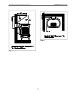
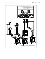
The Champlain cannot be vented jointly
with any other solid fuel or gas appliance. It
must be vented directly to the outside of the
building using a proper termination as listed
in the manual. Your Champlain Direct Vent
stove is approved for use with Simpson
Dura-Vent’s GS Direct Vent, AmeriVent
Direct, or Secure Vent systems. The venting
configurations are shown in Figures 10 - 12.
After determining the venting configuration
for your stove, select the vent system that
will accommodate your installation.
Caution: Make sure all stove and
termination cap clearances have been
observed per the Owner’s Manual.
Caution: Be sure there is no wiring or
plumbing in the chosen location.
Caution: Venting terminals shall not be
recessed into a wall or siding.
Note:
If further direction is needed for
installation, please refer to the venting
instructions, which are provided with the
venting system.
A
CCEPTABLE
D
IRECT
V
ENT
T
ERMINATION
C
AP
L
OCATIONS
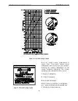
The vent/air intake termination clearances
above the high side of an angled roof are as
follows:
Roof Pitch
Feet Meters
Flat to 6/12
1
0.3
7/12 to 9/12
2
0.6
10/12 to 12/12 4
1.2
13/12 to 16/12
6
1.8
17/12 to 21/12 8
2.4
Listed below are components acceptable for
installation. The venting system must be
comprised of the appropriate venting
components as specified.
A
PPROVED
V
ENTING
S
YSTEM
C
OMPONENTS
*Component Description
90
0
Elbow
45
0
Elbow
6" Straight
9" Straight
12" Straight
24" Straight
36" Straight
48" Straight
11"-14
5/8"
Adjustable Pipe Length
Horizontal Vent Cap
Vertical Vent Cap
Snorkel 36”
Vinyl Siding Standoff 4 x 6
5/8”
Round Ceiling Support Wall
Thimble Covers
Wall thimble


