Page 20
12/12
Installing Weatherhoods
Installing Ducting from Weatherhoods to the
(HRV/ERV) Unit
The inner and outer liners of the flexible insulated duct
must be clamped to the sleeve of the weatherhoods (as
close to the outside as possible) and the appropriate port
on the HRV/ERV. It is very important that the fresh air in-
take line be given special attention to make sure it is well
sealed. A good bead of high quality caulking (preferably
acoustical sealant) will seal the inner flexible duct to both
the HRV/ERV port and the weatherhood prior to clamping.
To minimize airflow restriction, the flexible insulated duct
that connects the two outside weatherhoods to the
HRV/ERV unit should be stretched tightly and be as short
as possible.
Twisting or folding the duct will severely restrict airflow.
Hard (rigid) ducting which has been sealed and insulated
should be used for runs over 10’ (3.3m). Refer to local
building codes.
Intake Weatherhood Requirements
Observe the following when installing the intake weather-
hood:
1. Should be located upstream (if there are prevailing
winds)
2. At least 6’ (2m) from the exhaust weatherhood
3. At least 6’ (2m) away from dryer vents and furnace ex-
haust (medium or high efficiency furnaces)
4. A minimum of at least 6’ (2m) from driveways, oil fill
pipes, gas meters, or garbage containers
5. At least 18" (457mm) above the ground, or above the
depth of expected snow accumulation
6. At least 3’ (1m) from the corner of the building
7. DO NOT locate in a garage, attic or crawl space
8. AFTER installing the weatherhood, its outside perime-
ter must be sealed with exterior caulking
Exhaust Weatherhood Requirements
Observe the following when installing the exhaust
weatherhood:
1. At least 6’ (2m) from the ventilation air intake
2. At least 18" (457mm) above ground or above the depth
of expected snow accumulation
3. At least 3’ (1m) away from the corner of the building
4. Not near a gas meter, electric meter, or a walkway
where fog or ice could create a hazard
5. Not into a garage, workshop, or other unheated space
6. AFTER installing the weatherhood, its outside perime-
ter must be sealed with exterior caulking
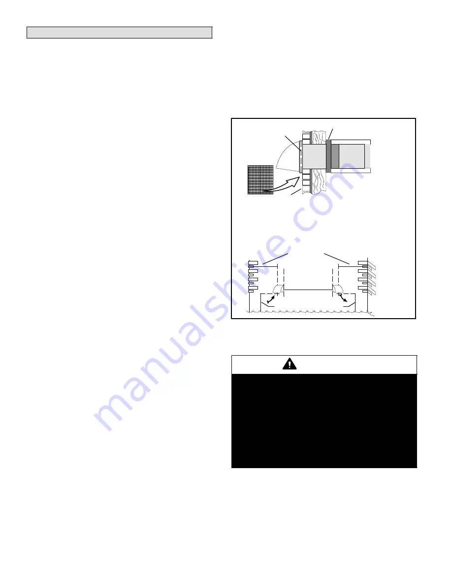
Weatherhoods
Fixed covered weatherhoods have a built−in bird screen
with a
¼
" (6mm) mesh to prevent foreign objects from en-
tering the ducting labeled SUPPLY and EXHAUST.
5" (127 mm) Part no.
92E66
6" (152 mm) Part no.
95P07
7" (203 mm) Part no.
17N11
ÑÑÑÑ
ÑÑÑÑ
ÑÑÑÑ
1. Thermal collar slides over galvanized sleeve of weatherhood.
2. Fasten thermal collar to belt.
3. Slide insulated flexible ducting over the weatherhood’s galvanized sleeve and fasten
to the thermal collar.
4. Hood is hinged to allow for easy access for cleaning screen.
12" galva-
nized pipe
supplied
Collar is supplied to ensure
vapor barrier is 100% sealed
to wall plate.
SCREEN
(side view)
EXTERIOR
WALL
1/4" (6mm)
SCREEN
(front view)
6’ (2m) min.
recommended
36" (1m) min.
recommended
OUTSIDE
CORNER
INSIDE
CORNER
18" (460Mm) min. recommended
SUPPLY
EXHAUST
Figure 17. Weatherhood Installation
CAUTION
Potential equipment malfunction or damage.
May require repairs and/or void warranty.
Snow accumulation may block airway of weather-
hoods. Install intake and exhaust weatherhoods at
least 18 inches (457 mm) above the ground or above
the depth of expected snow accumulation.
Install intake and exhaust weatherhoods with at
least 6 feet distance between openings to prevent
short circuit air routes. Local codes may require a
greater distance between openings.


