


17
U9B
A0137-7.0 en/de/fr
HBM
Important
Balancing resistors (for sensitivity adjustment) are mounted on a PCB inside a
colored shrinkdown plastic tubing on transducers with nominal (rated) load of
50 N, 100 N and 200 N. If the cable is to be shortened, you must solder the
PCB back into the connection cable according to the labels on the PCB.
6.3
Cable extension
Only use shielded, low‐capacitance measurement cables for extension. En
sure that connection is perfect, with a low contact resistance. We recommend
implementing extensions using six‐wire configuration to exclude changes to
the sensitivity.
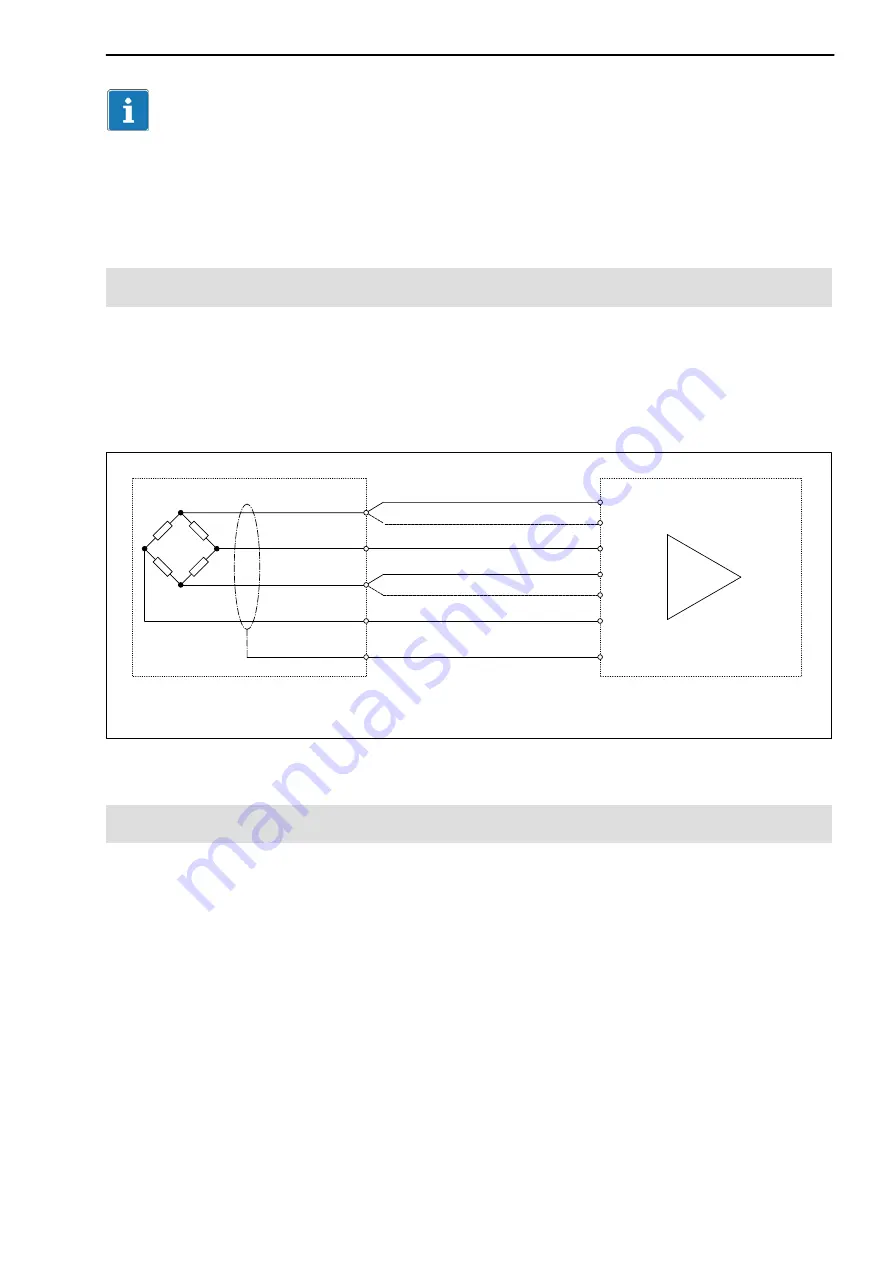
(red)
(black)
(blue)
(white)
Excitation voltage (+)
Excitation voltage (-)
Measurement signal (-)
Measurement signal (+)
Sense lead (-)
Sense lead (+)
Cable extension
(Six‐wire configuration)
Force transducer
(Four‐wire circuitry)
Shielding
Amplifier
(Six‐wire configuration)
Fig 6.2:
Transducer connection to amplifier with six‐wire configuration
6.4
EMC protection
Electrical and magnetic fields often induce interference voltages in the mea
suring circuit. Therefore:
•
Use shielded, low‐capacitance measurement cables only (HBM cables
fulfill both conditions).
•
Do not route the measurement cables parallel to power lines and control
circuits. If this is not possible, protect the measurement cable with e.g. steel
conduit.
•
Avoid stray fields from transformers, motors and contact switches.
•
Do not ground the transducer, amplifier and indicator more than once.
•
Connect all devices in the measurement chain to the same grounded
conductor.
Summary of Contents for U9B
Page 2: ...English Seite 3 22 Deutsch Page 23 44 Fran ais Page 44 66...
Page 22: ...U9B 22 A0137 7 0 en de fr HBM...
Page 44: ...U9B 44 A0137 7 0 en de fr HBM...
Page 67: ......