background image


USE ONLY HAYWARD GENUINE REPLACEMENT PARTS 

Page 22 of 36 

Super Pump VS Pump 

IS2603VSP  Rev-A 

6.6.


Configuration Menu 


Buttons 

 Screen  Used 

Comments 

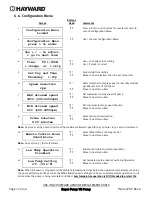
1.


< >


Press & hold < and > buttons for several seconds to 


unlock 

Configuration 

Menu 

2.


< >


Use > to enter Configuration Menu 


3.


4.


+ -


Use + to change clock setting 


< >


Use > if clock is correct 

5.


+ -


Adjust day/time setting 


< >


Move to next selection, then to next menu item 

6.


+ -


Select whether to display speed in rpm (Revolutions 


per Minute) or % of full speed 


< >


Move to next menu item 

7.


+ -


Set maximum running speed of pump 


< >


Move to next menu item 

8.


+ -


Set minimum running speed of pump 


< >


Move to next menu item 

9.


+ -


Select pump prime duration 


< >


Move to next menu item 

Note:

  User may set the pump to prime at the maximum allowed speed for 0-15 minutes in 30 second increments. 

10.


+ -


Select Stand Alone or Relay Control 


< >


Move to next menu item 

Note:

  See section 5.3 for more detail. 

11.


+ -


Enable or Disable Low Temp Operation 


< >


Move to next menu item 

12.


+ -


Set temperature to activate Low Temp Operation 


< >


Move to next menu item 

Note:

  When the pump is stopped and the ambient temperature drops below the operation temperature set point, 

the pump will prime and then run at the MAX allowed speed setting for 8 hours. Low temperature operation is 

not 

active when the pump is being remotely controlled.  

Low temperature operation is NOT intended to protect the 

Configuration Menu 

press > to enter


Set Day and Time 

Thursday   1:27p


Speed Selection 

rpm


MAX allowed speed 

3450 (600-3450rpm)


MIN allowed speed 

600 (600-3450rpm)


Prime Duration 

8:00 minutes


Remote Control Mode 

Stand Alone


Configuration Menu 

Locked


Time:   Th 1:27PM 

+ change  or  > skip


Use + / - to adjust, 

> go to next item


Low Temp Operation 

Disabled 

Low Temp Setting  

4ºC (39.2ºF) 

Summary of Contents for Super Pump VS SP2603VSP

Page 1: ...ermanent magnet motor Super Pump VS is easily installed either as a programmable stand alone pump or with a Hayward or third party controller and features an easy to use digital control interface that...

Page 2: ...Procedure 14 5 Wiring Diagrams 15 5 1 Input Power Wiring Required 15 5 2 Wall Mounted Digital Control Interface Wiring Optional 15 5 3 External Relay Speed Control Wiring Optional for remote selection...

Page 3: ...3 Removing the Ceramic Seat 27 9 4 Seal Installation 27 9 5 Replacing the Impeller and Diffuser 27 9 6 Replacing the Motor Assembly 28 10 Replacement Parts 28 10 1 Parts Diagram 28 10 2 Parts Listing...

Page 4: ...l Electric Code NEC USE OF NON HAYWARD REPLACEMENT PARTS VOIDS WARRANTY ATTENTION INSTALLER THIS MANUAL CONTAINS IMPORTANT INFORMATION ABOUT THE INSTALLATION OPERATION AND SAFE USE OF THIS VARIABLE SP...

Page 5: ...ARNING Failure to bond pump to pool structure will increase risk for electrocution and could result in injury or death To reduce the risk of electric shock see installation instructions and consult a...

Page 6: ...be in off position and filter manual air relief valve must be in open position Before starting pump all system valves must be set in a position to allow system water to return back to the pool Do not...

Page 7: ...ced hydraulic design Fully programmable with a self contained 24 hour clock and up to 8 custom speed and timer functions For enhanced pool management can be controlled by Hayward or third party pool a...

Page 8: ...ce every 24 hours Check with local requirements for the minimum turnover rate Running the pump at a lower speed may require running the pump for a longer period of time in order to meet the turnover r...

Page 9: ...ARNING Hazardous Pressure Pumps filters and other equipment components of a swimming pool filtration system operate under pressure Incorrectly installed and or improperly tested filtration equipment a...

Page 10: ...required by code Connect ground terminal to electrical service ground 3 Bond pump to pool structure Bonding will connect all metal parts within and around the pool with a continuous wire Bonding redu...

Page 11: ...e section 5 3 for more information regarding connecting Super Pump VS and third party non software compatible Hayward controls 3 Super Pump VS can communicate with and be controlled by Hayward pool an...

Page 12: ...he W S485 terminal tion The cabl t provided on ed for the cabl Figure 4 12 4 wall mount pla plate taking re DR9 on the mo ure 4 12 3 esume norma interface wal moving the Dig GENUINE RE Pump VS Pu part...

Page 13: ...12 2 Re USE ONLY H emoving the I F HAYWARD G Super P nterface Mou igure 4 12 3 A GENUINE RE Pump VS Pu unting Plate to Adding the Bl PLACEMENT ump o access the D lank Cover T PARTS Drive wiring co IS...

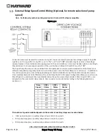
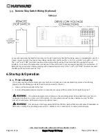
Page 14: ...elay contacts as shown in the External Relay Speed Control Wiring diagram See section 5 3 6 If the installation will use the remote stop feature of the drive connect the digital input terminals to the...

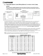
Page 15: ...ce Wiring Optional Figure 5 2 1 Connection wire must be rated for a minimum of 300V and may be up to 500 feet in length Use removable 4 position terminal block connectors for wiring connection to inte...

Page 16: ...ing relay contacts to select the speeds set in the Timer Menu see section 6 7 In addition to this section you may also consult the applicable pool control installation manual for electrical connection...

Page 17: ...otor drive PCB taking care to note the wire colors and corresponding numbers next to the connectors Terminal block must be installed with screws facing up to ensure proper connection When communicatin...

Page 18: ...d the SW200 DIP switch 1 must be ON 6 Startup Operation 6 1 Prior to Start Up If it is necessary to perform a water pressure test prior to initial use to ensure plumbing system is functioning properly...

Page 19: ...or ATTENTION Do NOT add chemicals to pool spa system directly in front of pump suction Adding undiluted chemicals may damage pump and voids warranty ATTENTION Before removing strainer cover 1 STOP PUM...

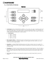
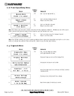
Page 20: ...hrough the setup menus when pressed The and arrow buttons are used to move between displays and to select parameters to edit and the and arrow buttons are used to change parameters 3 Status LEDs The C...

Page 21: ...uals 1 through 4 c Speed X Speed where X equals 1 through 4 4 Diagnostics Menu see section 6 9 to view product diagnostic information a Display Firmware Revision b Drive Serial Number c Motor Drive Fi...

Page 22: ...30 second increments 10 Select Stand Alone or Relay Control Move to next menu item Note See section 5 3 for more detail 11 Enable or Disable Low Temp Operation Move to next menu item 12 Set temperatu...

Page 23: ...s are to run 7 days per week 5 days per week Monday thru Friday or on a single day Monday thru Sunday Each timer is set up in this same manner When the pump is powered and the timers are set up the Ti...

Page 24: ...d without entering the Speeds Menu using the and arrow buttons to change the speed and then pressing the button to save the new speed setting 6 9 Diagnostic Menu Buttons Screen Used Comments 1 Use to...

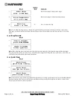
Page 25: ...operation the above message will be displayed The pump will stop within several seconds and will remain stopped until Stop Resume is pressed a second time at which point the pump will resume normal o...

Page 26: ...volume blower when air purging the pump filter or piping ATTENTION Allowing the pump to freeze with water in it will void the warranty ATTENTION Use ONLY propylene glycol as antifreeze in your pool sp...

Page 27: ...expose the impeller 9 2 Removing the Impeller 3 To prevent the motor shaft from turning secure using a 5 16 hex wrench on the motor shaft through the fan shroud on the back of the pump 4 Remove the im...

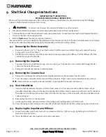
Page 28: ...isturb the diffuser gasket 14 Fasten assembly to pump strainer housing using the four 4 3 8 x 2 bolts Be sure housing gasket is in place and lubricated Replace if damaged Tighten bolts alternately and...

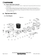
Page 29: ...X1600F5 Motor Mounting Plate 1 14 SPX0125z44 Motor Cap Screws Set of 4 1 15 SPX1600Z4 Housing Cap Screw 4 16 SPX2600G1 Mounting Foot Includes Screws 1 17 SPX1600Z52 Mounting Foot Screws Set of 2 1 18...

Page 30: ...asket loaded with debris Remove the strainer housing cover or the skimmer cover Clean the basket and refill the strainer housing with water Tighten the cover 5 Suction side clogged Contact a qualified...

Page 31: ...to the equipment pad 3 Foreign matter in the pump housing Loose stones debris hitting the impeller could be the cause Clean the pump housing 4 Motor bearings noisy from normal wear rust overheating o...

Page 32: ...ical Service for additional assistance Check System Processor failed Indicates that there is a problem with the processor in the motor drive and that the motor drive may need to be replaced Contact Ha...

Page 33: ...IS2603VSP Rev A DATE OF INSTALLATION ____________________ INITIAL PRESSURE GAUGE READING CLEAN FILTER _______________________ PUMP MODEL __________________ 12 Warranty 13 Product Registration Retain t...

Page 34: ...USE ONLY HAYWARD GENUINE REPLACEMENT PARTS Page 34 of 36 Super Pump VS Pump IS2603VSP Rev A THIS PAGE INTENTIONALLY LEFT BLANK...

Page 35: ...USE ONLY HAYWARD GENUINE REPLACEMENT PARTS Page 35 of 36 Super Pump VS Pump IS2603VSP Rev A THIS PAGE INTENTIONALLY LEFT BLANK...

Page 36: ...__________________________ Type of Pool Concrete Gunite Vinyl Fiberglass Other_____________________________ New Installation Replacement Installation for In Ground Spa FCC Compliance Statement This de...

Reviews: